
Fire Alarm Using Thermistor circuit

The fire alarm circuit operates on the principle of temperature monitoring through the thermistor, which is a type of resistor whose resistance varies significantly with temperature changes. The thermistor is positioned in an environment where it can effectively sense heat, such as near potential fire sources.
When the ambient temperature rises due to a fire, the thermistor's resistance decreases, leading to an increase in current flow through the circuit. This change in current can be detected by a comparator or a microcontroller, which is configured to trigger an alarm when the current exceeds a certain threshold.
The circuit may include additional components such as a power supply, typically a 5V or 12V source, a comparator IC like the LM393, and a buzzer or alarm indicator. The thermistor is connected in a voltage divider configuration with a fixed resistor, allowing for a measurable voltage change that corresponds to the resistance change in the thermistor.
To ensure reliability, the circuit can be designed with hysteresis to prevent false alarms due to minor temperature fluctuations. This is achieved by incorporating feedback from the output of the comparator back to the input, creating a stable threshold for activation.
Overall, this fire alarm circuit is designed for ease of construction and reliability, making it suitable for various applications in fire detection systems. It is essential to follow safety standards and guidelines during assembly and installation to ensure effective operation in real-world scenarios.In this fire alarm circuit, a Thermistor works as the heat sensor. When temperature increases, its resistance decreases, and vice versa. At normal temperature, the resistance of the Thermistor (TH1) is approximately kilo-ohms, which reduces to a few ohms as the temperature increases beyond 100 C. The circuit uses readily available components and can be easily constructed on any general-purpose PCB..
🔗 External reference
Related Circuits
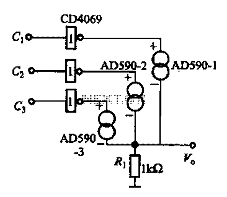
The AD590 is illustrated in a basic application circuit. As the AD590 provides a current output, a series resistance is used to convert this output current into a voltage. In the circuit, RP serves as the output voltage (vo)...

The 555 timer circuit, regardless of the manufacturer, has a consistent internal structure and performance. Various manufacturers produce different models of the 555 timer, including MC555, CA555, XR555, LM555, as well as domestic models like SL555, FX555, and 5G1555....

The Dish Network 322 Satellite Receiver enables television viewing of two distinct programs in two separate locations. This is a schematic block diagram illustrating an exemplary circuit logic diagram. The receiver is capable of predicting the elevation angle for...

The PLL synthesizer oscillator circuit is a feedback loop consisting of a reference oscillator, phase comparator, loop filter, voltage-controlled oscillator, programmable frequency divider, and various other components. In this circuit, the reference oscillator employs a crystal oscillator (OSC) to...

This circuit is a simple mixer circuit that can mix two signal channels into one output channel. It utilizes a codec circuit to convert stereo audio to mono audio. The main component in this circuit is a FET, specifically...
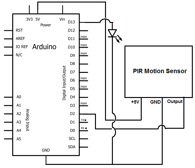
Once the motion sensor detects motion, the Arduino can be programmed to activate an LED, turn on a motor, sound a buzzer, etc. In this circuit, for simplicity, an LED will be turned on when the motion sensor detects...