
Flash Slave Trigger

The flash slave circuit typically comprises a phototransistor, which acts as the light sensor. When the primary flash emits light, the phototransistor detects this flash and generates a corresponding electrical signal. This signal is then processed by a trigger circuit, which activates the additional flash units. The delay introduced between the detection of the primary flash and the triggering of the supplementary flashes ensures that the additional units fire in synchronization with the master flash, providing a cohesive lighting effect.
The sensitivity adjustment feature is crucial for adapting to varying lighting conditions. By incorporating a variable resistor or potentiometer in the circuit, users can fine-tune the threshold at which the phototransistor responds to light. This adjustment allows the flash slave to function effectively in environments with different ambient light levels, ensuring reliable operation even when the master flash is less intense than usual.
In practical applications, the flash slave circuit can be integrated into photography setups where multiple light sources are required for balanced illumination. This setup is particularly beneficial in portrait photography, product photography, and any scenario where controlled lighting is essential. The ability to synchronize multiple flashes enhances the overall quality of the images captured, allowing for creative lighting techniques and effects.Flash slaves are used when you need to supplement one flash unit with one or several more. This slave trigger simply triggers those other units. It does this by "seeing" the first flash (using a phototransistor) and triggering the other flashes a few microseconds later. The sensitivity of the circuit is adjustable to compensate for ambient light o r dimmer than usual master flashes. 🔗 External reference
Related Circuits

The circuit operates with a 220V mains supply through a diode (VDi) configured as a half-wave rectifier. Capacitors C1 to C3 are charged, and due to the lack of full synchronization in the charging process, a pilot thyristor is...

The 2N6101 transistor should be mounted on a small heatsink. The 300 kΩ resistor controls the off period and might need to be adjusted if the transistor gains are high. The 100 kΩ resistor controls the on period. The 2N6101...

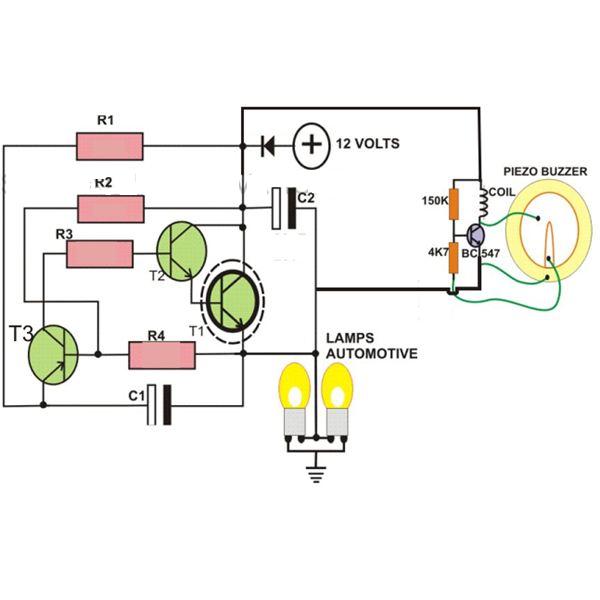
The circuit consists of a relaxation oscillator created by Q1 and an SCR flip-flop formed by Q2 and Q3. When the supply voltage is applied to the circuit, the timing capacitor C1 charges to the firing point of the...

This is a 220V LED flasher circuit designed as a reliable alternative to thermally-activated switches for flashing Christmas tree lamps. The circuit is cost-effective and easy to assemble. Schematic diagram: Component Parts: R1 10Ω. The 220V LED flasher circuit operates...

The timing components are R1, R2, and C1. C1 is a bypass capacitor used to reduce the effects of noise. At start-up, the voltage across C1 is less than the trigger level voltage (1/3 Vcc), causing the timer to...
This circuit is designed to create a flasher unit for a motorbike. It is a simple turn signal flasher circuit that can be easily built and installed in any two-wheeler for the desired functionality. The circuit uses only two...