
Flash triggering circuit


The circuit consists of a 9V battery connected to a MAX603 linear voltage regulator, which steps down the voltage to 5V for the operation of the circuit. An infrared LED and a phototransistor form a light detection system, where the phototransistor outputs 5V when the LED is on and drops when the light beam is interrupted. This output is fed into the trigger pin of a 555 timer IC. The 555 timer is configured in monostable mode, producing a high output for a duration determined by the charging of a capacitor through a variable resistor. The output of the 555 timer is connected to a DM7473 flip-flop, which toggles its output states based on the clock input from the 555 timer. The flip-flop's outputs control NPN and PNP transistors, which act as switches to activate a PVA33N solid-state relay that fires the flash unit. The reset mechanism for the flip-flop ensures that the circuit can be reused for subsequent triggers. The design allows for precise timing in high-speed photography applications, effectively managing voltage levels and circuit states to control the flash firing.My first project after assembling an electronic design lab was to build a flash trigger that I could use for high-speed photography. I thought it would be useful to share not only the finished product but also the reasoning that went into its design — in the hopes that others will learn from and improve upon it.
When I first thought about building a flash trigger, I did some research to see if anyone had a ready-made schematic available. It turns out that Johannes Eriksson has done just that — and kindly provided a schematic and a brief overview of the circuit.
I pored over the circuit until I had a tentative understanding of how it worked, then set about designing my own. Since our circuit will use 5V all over the place, our first task is to turn a 9V battery into the voltage we need.
Maxim’s MAX603 linear regulator is a handy chip that will output 5V given a wide range of input voltages — with a few supporting capacitors, the chip will do all the work for us. I simply followed the suggested circuit in the datasheet.Next, I needed a circuit that would output a change in voltage when a light beam is interrupted.
I turned to Jameco for an infrared LED and matching phototransistor. Fairchild Semiconductor has a good application note about designing with phototransistors — essentially, a phototransistor allows current to flow only when light is present. A large resistor between the phototransistor and ground causes 5V to be output when light is present, but pulls the output to ground when the beam is interrupted.Unfortunately, there’s bound to be ambient light hitting the phototransistor even when the LED beam is interrupted. The phototransistor may only reduce the voltage at its output by 1V when the beam is interrupted — we normally output 5V, and the 555 timer won’t trigger until the voltage dips below 1.67V, so the change in voltage won’t even be noticed.
However, we can divert some of the current from the output of the phototransistor to ground with a variable resistor — this allows us to subtract a constant voltage from the circuit’s output. The output from our phototransistor circuit is connected to the 555 timer’s trigger pin. When it detects a low pulse, it puts 5V on pin 3 and begins to charge the .22uF capacitor on the left.
The resistor and capacitor on the left form an RC circuit — the lower the resistance of the variable resistor, the faster the capacitor charges. When the capacitor is nearly full, the 555 drops pin 3 back to ground.Since the 555 timer’s output sits at 5V for an amount of time dependent on the variable resistor to the left, we can use it to delay the time between the 555 being triggered and our flash being fired.
In order to do so, we need a component which will wait for the output to go from ground to 5V and back to ground again — and that’s where our flip-flop comes into play.The DM7473 flip-flop has two inputs (pins 3 and 14), two outputs (12 and 13), and a clock input (1). Here’s how it works: each time the clock input goes to 5V then back to ground, the outputs change. One output is either at 2V or at ground, and the other is always the opposite. By connecting both inputs to 5V, we can make the outputs toggle back and forth each time the clock input is pulsed.In order to make use of its outputs, we first need to put them in a known state.
Pin 2 of the flip-flop is a reset pin — when it is connected to ground, the chip resets its outputs so that pin 12 is at ground and pin 13 is at 2V. The resistor and capacitor connected to the reset pin form an RC circuit, like the one connected to the 555 timer; when power is applied, the pin will start out at ground and slowly (depending on the capacitor and resistor values) rise to 5V as the capacitor charges.With power on, the flip-flop is now waiting for a pulse to come in on pin 1.
It triggers on the falling edge of this pulse — not when it goes from ground to 5V, but when it falls from 5V back to ground. (Recall that we wanted nothing to happen while the 555 timer’s output was high, since that served as our delay.) When this happens, the outputs will invert — pin 12 will go from ground to 2V, and pin 13 will go from 2V down to ground.Each output is connected to the base of a transistor: an NPN transistor at pin 12, and a PNP transistor at pin 13.
An NPN transistor allows current to flow from its collector (top of the transistor symbol in this case) to its emitter (at the bottom) when voltage is present at its base. Likewise, a PNP transistor allows current to flow when its base is at ground. The transistors act like switches in our circuit — when pin 12 outputs 2V, its transistor will allow current to flow between its two pins, and likewise the transistor at pin 13 will conduct current when its base goes to ground.Let’s run through the flip-flop’s state one more time.
When it powers up, its outputs are set such that pin 12 is at ground and pin 13 is at 2V — so both transistors act like open switches. At the end of a pulse from the 555, the output pins invert and both transistors turn on.The PNP transistor is connected to a PVA33N solid-state relay.
This is a special type of switch which allows a large voltage (the flash, in this case) to be controlled by a much smaller voltage. Internally it works much like our light trigger — pins 2 and 3 of the PVA33 are connected to an LED inside the case.
When current flows between these pins, the LED activates a phototransistor and short-circuits pins 5 and 6.Luckily for us, flash units fire when their pins are connected together. A simple connector from Adorama, connected to pins 5 and 6 of the PVA33, will allow the flash to fire when the PNP transistor below the relay turns on.Now that our flash has fired, we want to reset the circuit so that it can be triggered again.
Remember how we can reset the flip-flop by pulling pin 2 back to ground? The NPN transistor at pin 12 creates yet another RC circuit when it turns on, discharging the 220uF capacitor just slowly enough to be sure that the flash fired. When the capacitor has discharged, the flip-flop resets itself and both transistors turn off.Putting it all togetherNow that we’ve dealt with the details, let’s look at the circuit at a high level.
The phototransistor in our light trigger is normally lit up by the LED, so it conducts 5V to the 555 timer’s trigger input. When the light beam is broken, it stops conducting current and the input voltage goes low.When the 555 sees a low voltage at its trigger input, it puts 5V on pin 3 and the .22uF capacitor begins to charge at a rate determined by the variable resistor above it.
When the capacitor is charged, the 555 brings pin 3 back to ground.When the flip-flop sees pin 1 go from low to high and back to low again, it reverses the state of pins 12 and 13 (from low to high, or from high to low). This activates both transistors — one fires the flash by allowing current to flow through the PVA33 relay, while the other quickly bleeds current out of the capacitor connected to the flip-flop’s reset pin.
When this capacitor has discharged, the flip-flop resets and the transistors turn off.Now, instead of outputting 5V normally, we can divert some current to ground until we’re only outputting 2V. A 1V drop in voltage will reduce our output to 1V, which is low enough to trigger the 555.IntroductionWhen I first thought about building a flash trigger, I did some research to see if anyone had a ready-made schematic available.
It turns out that Johannes Eriksson has done just that — and kindly provided a schematic and a brief overview of the circuit. I pored over the circuit until I had a tentative understanding of how it worked, then set about designing my own.
🔗 External reference
Related Circuits
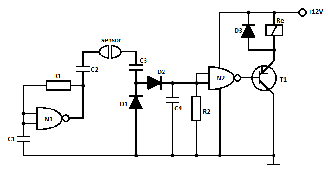
This is a straightforward liquid detector that utilizes a relay to activate an evacuation mechanism. It can be employed for water or any liquid that conducts electricity. Any PNP transistor capable of handling the relay current can be used....
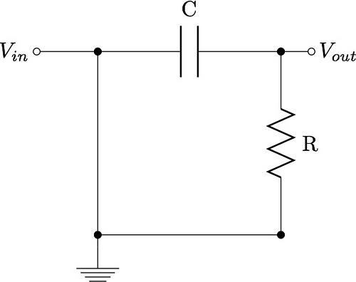
This guide aims to demonstrate the construction of various filter circuits, specifically low pass and high pass filters, along with additional details. The construction of filter circuits is essential in many electronic applications, as they allow for the selective passage...

The circuit utilizes the LM324 as a band-pass filter and the LB1405 as a driver for a five-band spectrum display. The selected frequency harmonics are centered at 100 Hz, 330 Hz, 1 kHz, 3.3 kHz, and 10 kHz. The...

Although labelled as distortion, this is a soft clipping device, using germanium diodes. It's a good example of how little you need for a good basic sound. You could easily swap (or switch) these diodes to silicon types for...
Replacing the LC modulation circuit with an active filter allows for the elimination of large and costly inductance coils in frequency shift key control demodulators. This approach not only reduces the size of the circuit but also enhances the...
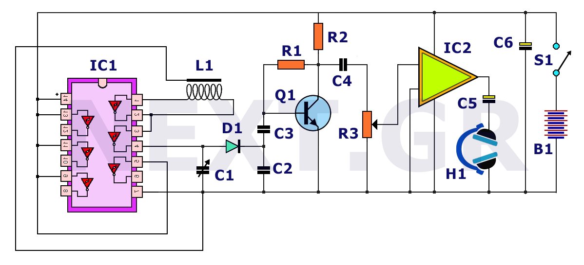
The principle behind a metal detector is quite simple. This is demonstrated by the following circuit, which shows that a metal detector can be constructed quickly with a few readily available components. This metal detector circuit can detect a...