
Passive Filter Circuits

The construction of filter circuits is essential in many electronic applications, as they allow for the selective passage of signals based on frequency. Low pass filters (LPF) enable signals with a frequency lower than a certain cutoff frequency to pass through while attenuating higher frequencies. Conversely, high pass filters (HPF) permit signals with frequencies higher than a specific cutoff frequency to pass while blocking lower frequencies.
A typical low pass filter can be designed using passive components such as resistors and capacitors (RC filter). The simplest form consists of a resistor (R) connected in series with the input signal and a capacitor (C) connected in parallel to the output. The cutoff frequency (fc) is determined by the formula:
fc = 1 / (2πRC)
For example, if a resistor of 1 kΩ is used in conjunction with a capacitor of 100 nF, the cutoff frequency would be approximately 1.59 kHz.
On the other hand, a high pass filter can also be constructed using an RC configuration, but with the capacitor placed in series with the input signal and the resistor connected to the ground. The cutoff frequency for a high pass filter is also given by the same formula:
fc = 1 / (2πRC)
In this configuration, the same resistor and capacitor values would yield the same cutoff frequency, but the behavior of the circuit would be opposite, allowing frequencies above the cutoff to pass while attenuating those below it.
In addition to the basic RC filters, more complex filter designs such as active filters using operational amplifiers can be implemented to achieve sharper roll-offs and better performance characteristics. Active filters can provide gain, improve input impedance, and reduce the effects of component tolerances.
Overall, understanding and implementing low pass and high pass filters is fundamental for engineers and hobbyists working with signal processing, audio applications, and communication systems. Proper design and analysis of these filters are crucial for achieving desired performance in various electronic circuits.This instructable is intended to show you how to make several different filter circuits, in particular, low pass and high pass filters, along with a.. 🔗 External reference
Related Circuits

This second-order low-pass filter utilizes a 741 operational amplifier and can be tuned from 2.5 kHz to 25 kHz. The circuit is beneficial in audio and tone control applications. R1 and R2 are ganged potentiometers. The described circuit features a...
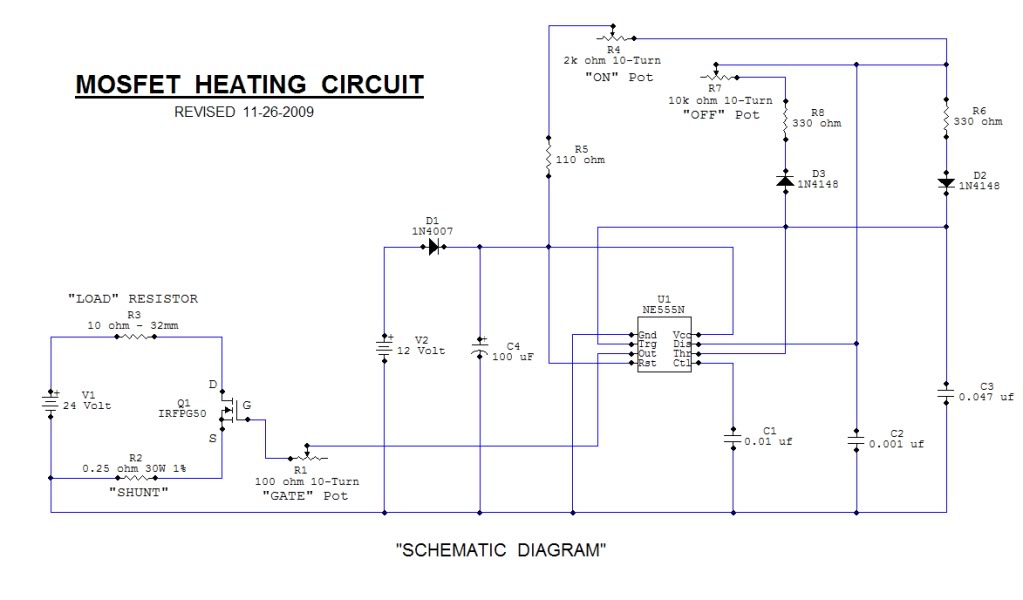
This open-source thread focuses on the development of a "MOSFET Heating Circuit," which is a modified version of an existing design. The MOSFET Heating Circuit is designed to efficiently manage and control heating elements using MOSFET technology. MOSFETs (Metal-Oxide-Semiconductor Field-Effect...
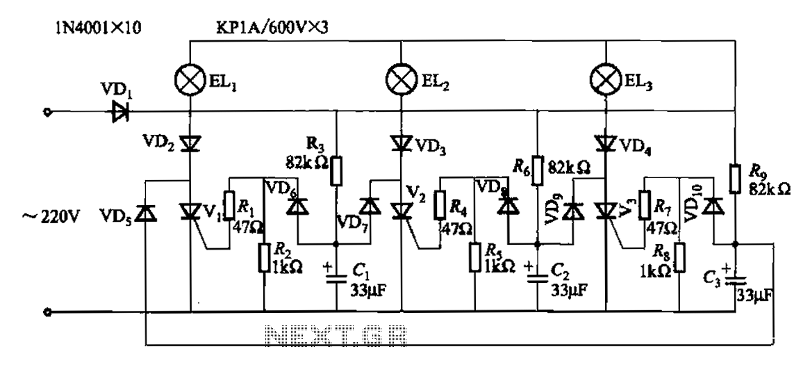
The circuit operates with a 220V mains supply through a diode (VDi) configured as a half-wave rectifier. Capacitors C1 to C3 are charged, and due to the lack of full synchronization in the charging process, a pilot thyristor is...
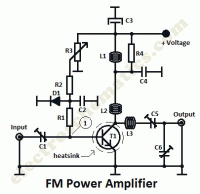
This is a 1 watt FM amplifier with a robust design that can be used to amplify an RF signal in the 88 to 108 MHz band. It is highly sensitive when utilizing quality RF power amplifier transistors, trimmers,...
Infrared remote controls are using a 32-56 kHz modulated square wave for communication. These circuits are used to transmit a 1-4 kHz digital signal (OOK modulation) through infra light (this is the maximum attainable speed, 1000-4000 bits per sec)....

This game can be played individually or with friends. The circuit consists of a timer IC, two decade counters, and a display driver paired with a 7-segment display. The objective of the game is straightforward: the player who reaches...