
flashing leds kit

This kit is designed for ease of assembly and user-friendly operation, making it suitable for both beginners and experienced electronics enthusiasts. The layout of the circuit board is optimized to minimize assembly errors, with clear markings and ample space between components. The silk-screened outlines not only aid in component placement but also contribute to a visually organized board, enhancing troubleshooting and maintenance.
The inclusion of plated-through holes for the component mounting ensures a robust connection, which is particularly beneficial in applications where the board may be subjected to mechanical stress or thermal cycling. The design choice to use large, well-spaced circuit pads further simplifies the soldering process, allowing for better heat dissipation during soldering and reducing the likelihood of cold solder joints.
The adjustable flash timing feature, controlled by the two potentiometers, provides flexibility in the operation of the LEDs. This allows users to customize the visual effects according to their preferences or project requirements. The ability to slow down or speed up the flashing of the LEDs enhances the versatility of the circuit, making it applicable in various contexts, such as decorative lighting, indicators, or educational projects demonstrating basic electronic principles.
Overall, this kit offers a comprehensive learning experience, combining practical assembly skills with the fundamentals of circuit design and LED operation.This kit includes a completely illustrated instructions and circuit schematic. Components are adequately spaced for easy assembly and value identification on the board. The circuit board has silk screened outlines for component p lacement and circuit pads on the solder side of the board are large and well spaced for easy soldering. Even the component mounting holes are plated through, making it easier to solder good connections and greatly reducing the odds of causing board damage in the event that a component placement correction might be required.
Two variable resistors (pots) allow independent adjustment of the flash timing of each LED. Rotate the pots counter-clockwise for slower LED flashing, or clockwise to flash the LED`s faster. 🔗 External reference
Related Circuits
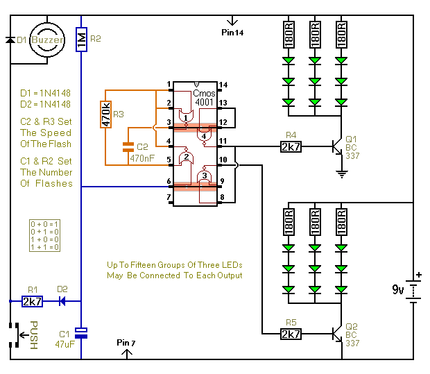
When the push switch is activated, the buzzer sounds, and the LEDs start to flash. For the hearing members of the household, the buzzer functions as a standard doorbell, providing reassurance to the visitor that the doorbell is operational....

This circuit operates two LED strips in pulsing mode, i.e. one LED strip goes from off state, lights up gradually, then dims gradually, etc. while the other LED strip does the contrary. Each strip can be made up from...

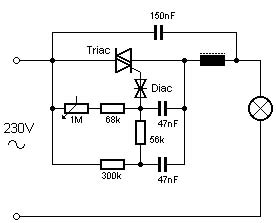
An AC mains operated single LED flasher circuit is constructed using the widely utilized CMOS timer chip TLC555. The entire circuit is powered directly from the 230VAC grid supply via a capacitive potential divider and associated components. This compact...
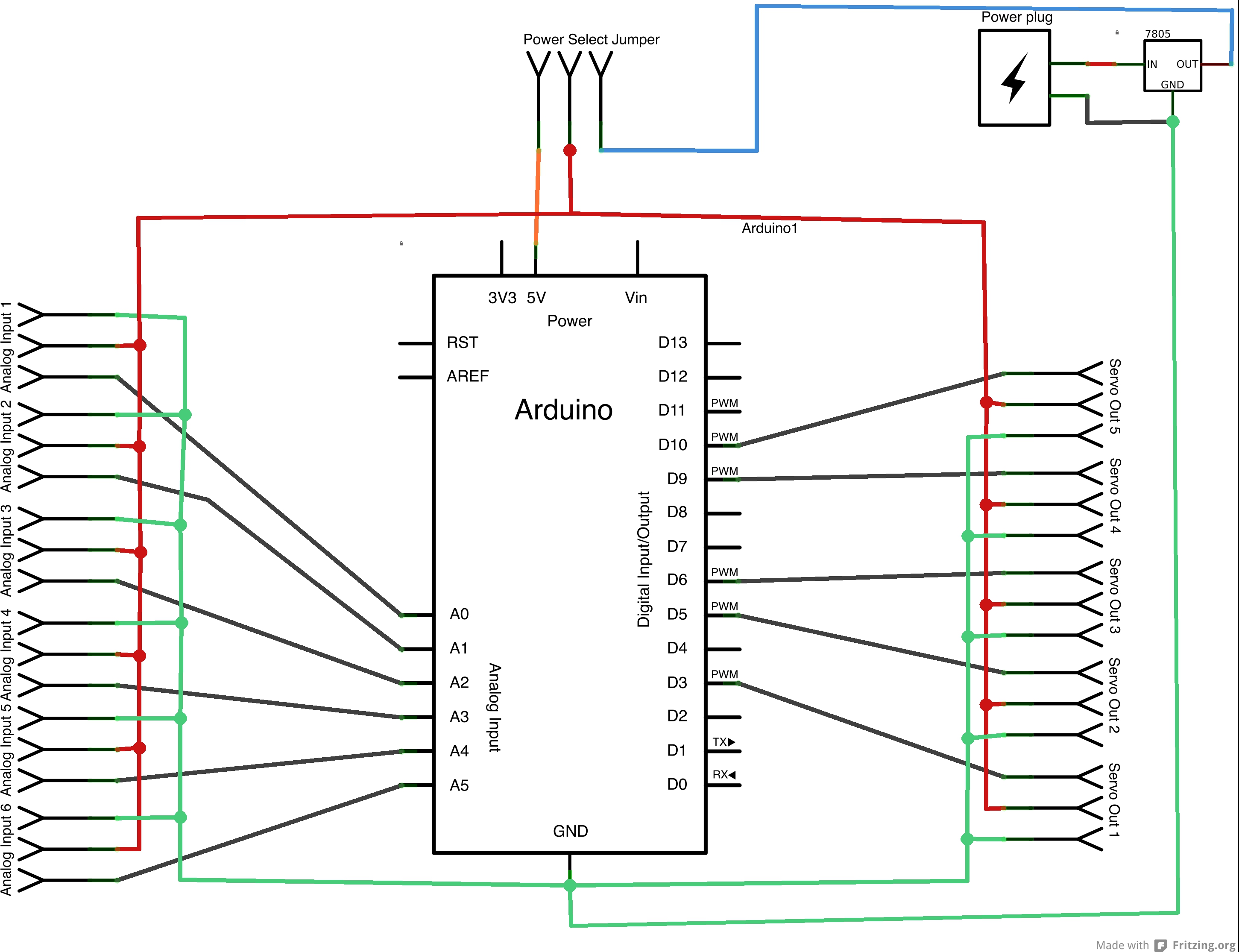
The Hakkit robotics shield serves as a breakout kit for the Arduino Uno R3. When assembled, the shield provides five standard servo headers that utilize the PWM pins on the Arduino and expands the analog pins to offer six...

7W Mono Audio Amplifier Kit - This compact amplifier is designed around the TDA2003 integrated circuit, which can provide 7 watts of audio power into a 4-ohm load. The 7W Mono Audio Amplifier Kit utilizes the TDA2003 IC, a popular...
Colour temperature refers to the tonal quality or shade of light. White light, for instance, is subjective and available in various hues. This guide aims to assist in identifying the most suitable shade for specific situations. A "warm" white...