
220V Flashing LED Circuit

The circuit operates on the principle of utilizing the TLC555 timer in an astable configuration, which allows it to generate a continuous square wave output. The timing components, R2, R3, and C3, are critical in setting the frequency of the oscillation, which can be adjusted by varying these component values. The capacitive potential divider is an essential part of the design, as it reduces the high AC voltage from the mains supply to a lower level suitable for the operation of the TLC555.
The red LED (D5) serves as the visual indicator in this circuit, flashing at a frequency determined by the timer. The reverse mode operation means that the LED is connected in such a way that it receives current when the output of the timer goes high, creating a flashing effect. Resistor R4 is crucial in preventing excessive current from damaging the LED and ensuring the longevity of the circuit.
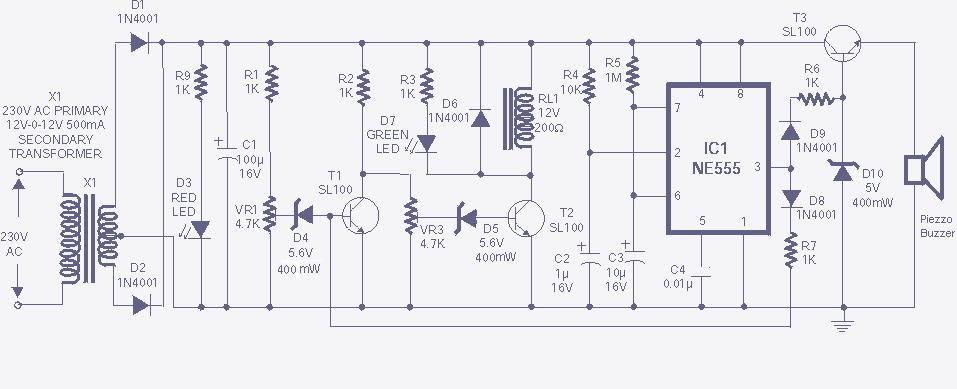
In practical applications, this LED flasher circuit can be used in various settings where visibility is important, such as safety markers on roads or as indicators for switches in dimly lit areas. The compact size of the circuit allows for easy integration into existing structures or devices, making it a versatile solution for enhancing visibility and safety.AC mains operated single LED flasher circuit, built using the popular CMOS timer chip TLC555 is shown below. The whole circuit is powered directly by the grid supply of 230VAC through a capacitive potential divider and associated components.
This minuscule Power LED Flashing circuit can be easily fit inside a very small plastic enclosure. The 220V flashing led circuit can be incorporated into a roadside/parking ground lane marker bollard, or used as a warning for other obstacles such as fences, scaffolding tubes, etc. It can also be suspended from light/fan switch pull-cords to make them easy to find in the dark. IC1 is here wired as a low frequency free-running oscillator, whose frequency is determined by the values of timing components R2, R3 and C3.
With the values and configuration shown, IC1 works like a narrow pulse width square wave oscillator source, giving very short positive pulses at its output pin3. Note that, IC1 is used to drive a 10mm red LED (D5) in reverse (ie sinking) mode. Resistor R4 limits the current flow through D5 and hence, through IC1. 🔗 External reference
Related Circuits
The high and low voltage cut-off with delay and alarm circuit, along with its circuit diagram, is explained in this post. The high and low voltage cut-off circuit is designed to protect electrical devices from damage caused by excessive voltage...

The LM1036 is a DC-controlled circuit designed for adjusting bass, treble, balance, and volume in stereo applications, particularly in car radios, televisions, and audio systems. An additional control input enables the implementation of loudness enhancement. Four control inputs facilitate...

The circuit illustrates a TL494 pulse width modulated step-down converter schematic. This circuit allows for testing of line regulation, load regulation, output ripple, short circuit current, and efficiency under various input voltage conditions. A detailed table of these tests...
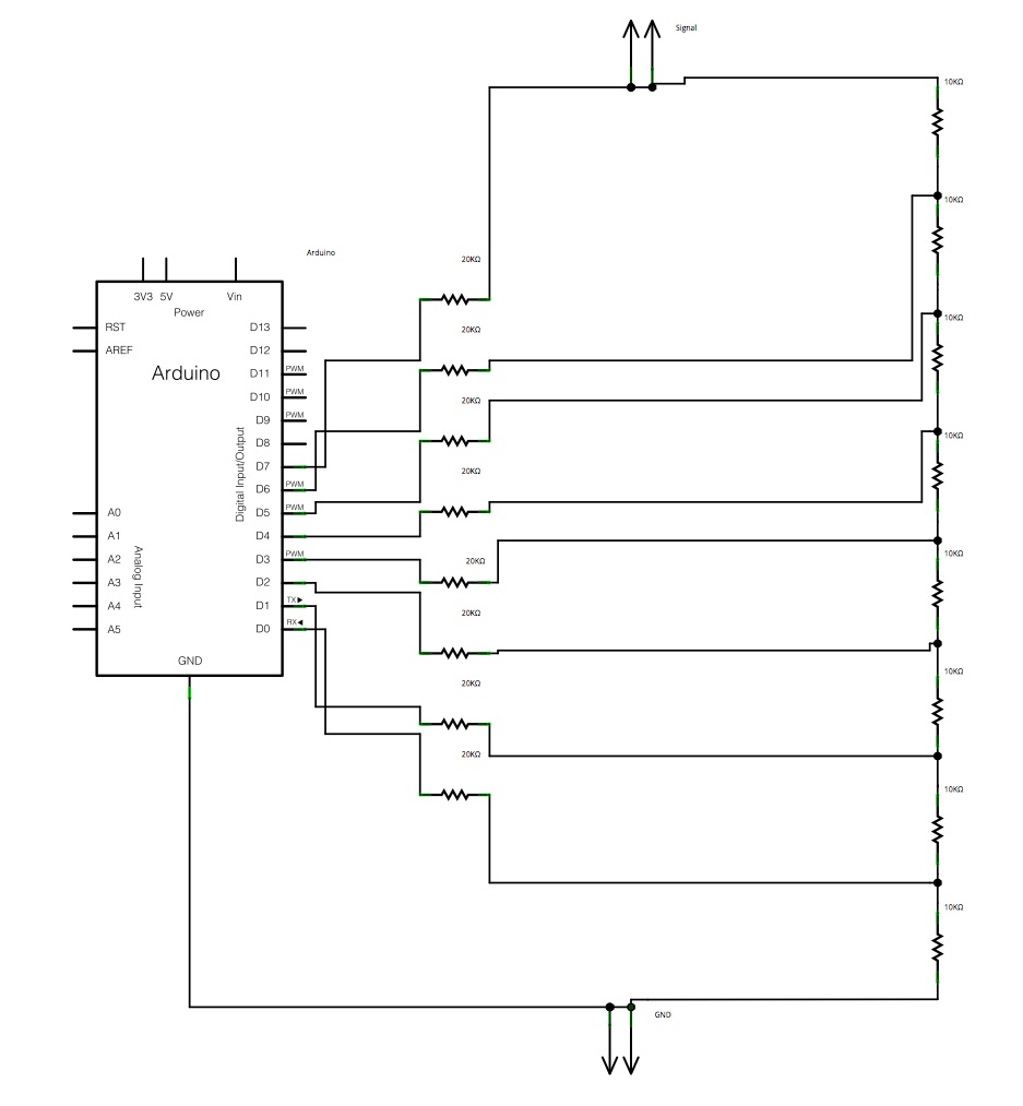
The main concept is to space the time intervals to increment the DAC output values. There are 256 levels since there are 8 digital outputs from the Arduino board. Therefore, for an 8-bit resolution and a 50-second ramp time,...
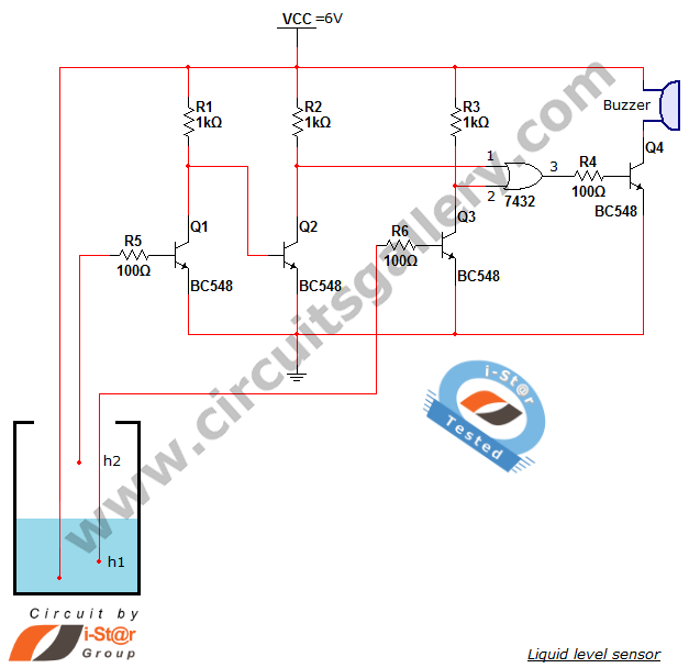
A variety of small electronic projects related to water level sensors have been posted in the Circuits Gallery. This particular project is designed for school students to detect the water level within a water tank or any other water...

This circuit is a simple mixer circuit that can mix two signal channels into one output channel. It utilizes a codec circuit to convert stereo audio into mono audio. The circuit can also increase the number of channels by...