
Flashing light controller with LM567 production

The circuit described employs a capacitive step-down voltage regulator, which is designed to convert a higher AC voltage into a stable lower DC voltage suitable for powering the LM567 integrated circuit. The components Cl, VDI, VD2, and C2 work together to ensure that the voltage is regulated to approximately 8V DC. The inclusion of a rectifier allows for the conversion of AC to DC, which is essential for the operation of the LM567.
The circuit also incorporates an ultra-low frequency oscillator, formed by the combination of resistors R3, RP, and capacitor C3. The frequency of oscillation is determined by the formula 1/(R3 + RP)C3, indicating that both the resistance values and the capacitance will affect the frequency output. This oscillator produces a square wave signal that can be utilized for various applications, including the control of an output device such as an H lamp.
The output from the oscillator is taken directly from a point in the circuit located 5 feet away, allowing for flexibility in the physical arrangement of components. The use of R2 silicon to control the gate enables the circuit to turn the H lamp on and off, creating a flashing effect. By adjusting the potentiometer RP, the user can fine-tune the resistance, thereby altering the frequency of the flashing light emitted by the H lamp. This feature allows for dynamic control over the visual signaling provided by the lamp, which can be useful in applications requiring attention or indication.
Overall, this circuit design combines voltage regulation with oscillation and control capabilities, making it suitable for various electronic applications where stable power and visual signaling are required. Cl, VDI, VD2, C2 composed of simple capacitive step-down voltage regulator circuit + rectifier output of about 8v DC voltage for LM567 electricity. 5,6 feet manifold connected resistors R3, RP and capacitor C3 form a frequency of II/(R3 + RP) C3 ultra-low frequency oscillator, the oscillation signal output directly from the 5 feet, can be added by R2 silicon vs control gate, so that the gap vs turned on and off, it can make the H lamp flashing light. Adjust the potentiometer resistance of RP, you can adjust the flashing frequency of lamp H rate.
Related Circuits
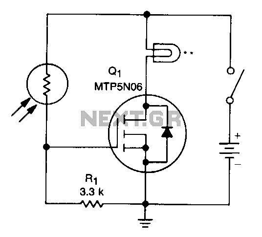
A school drama required lamps that automatically turned on and off in sync with the spotlights. The lamp switching system needed to be wireless, durable, reliable, simple, and cost-effective. With the stage and spotlights turned off, minimal light reaches...
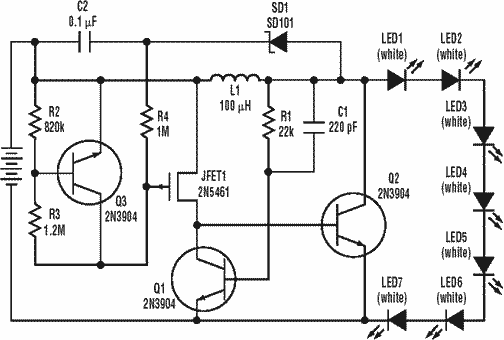
A low power, long-life LED flashlight circuit. Electronic Design proposed a simple circuit to resolve this in a recent article. The front end of their circuit draws less than a milliamp of extra current. The described LED flashlight circuit is...
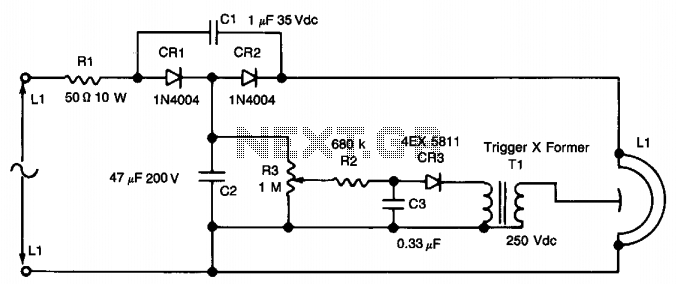
This circuit employs a voltage doubler configuration using diodes CR1 and CR2 to achieve approximately 280 V DC across capacitor C1. Capacitor C2 and resistor R3 create a voltage divider to produce a DC voltage that charges capacitor C3...
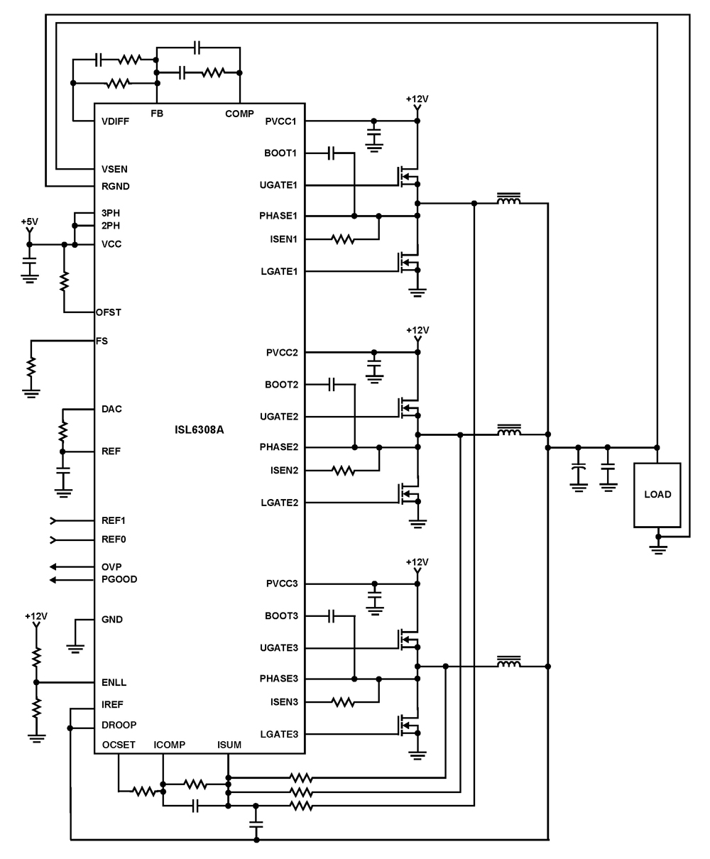
The ISL6308A is a three-phase PWM control integrated circuit (IC) equipped with built-in MOSFET drivers. It delivers precise voltage regulation suitable for various applications, including high current low voltage point-of-load converters, embedded systems, and other general low voltage medium...
The widespread application of Flash technology in microprocessors has led to significant advancements in the development and utilization of one-chip computers. Designers have transitioned from traditional in-circuit emulators (ICE) and JTAG interfaces to more cost-effective and user-friendly development methods....
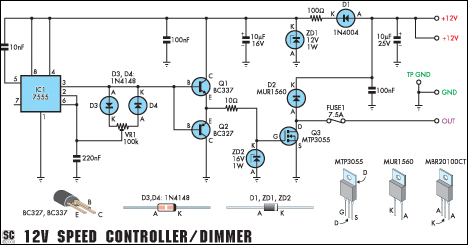
This circuit functions as a speed controller for a 12V motor with a continuous rating of up to 5A or as a dimmer for a 12V halogen or incandescent lamp rated up to 50W. It adjusts the power to...