
Disco-strobe light

The circuit operates on the principle of voltage doubling, where the diodes CR1 and CR2 are arranged to rectify and double the input AC voltage. The configuration allows the circuit to efficiently convert low-voltage AC into a higher DC voltage suitable for various applications. Capacitor C1 stores the high voltage, while the voltage divider formed by C2 and R3 is essential for regulating the output voltage to a desired level.
Capacitor C2 plays a crucial role in stabilizing the voltage across the divider, ensuring that the output remains consistent despite variations in load or input voltage. Resistor R3 serves to limit the current flowing through the divider, protecting the components from potential overloads.
The charging of capacitor C3 through resistor R2 indicates its function in smoothing the output voltage, providing a more stable DC supply. The timing of the charging process is influenced by the values of R2 and C3, which can be adjusted to tailor the response time and output characteristics of the circuit.
Furthermore, the activation of diode CR3 introduces a critical event in the circuit's operation. When CR3 conducts, it allows the high voltage from transformer T1 to be transferred to inductor L1. This process is vital for applications requiring inductive kickback or energy storage, as L1 can store energy and release it when needed, enhancing the overall efficiency of the circuit.
In summary, this circuit design effectively utilizes a voltage doubler and additional components to generate a high DC voltage while incorporating voltage regulation and energy storage features. The interplay between capacitors, resistors, and inductors creates a robust system that can be adapted for various electronic applications.This circuit uses a voltage doubler CR1 and CR2 to obtain about 280 V dc across Cl. C2 and R3 form a voltage divider to obtain a dc voltage to change C3 thru R2. When CR3 fires, a high voltage is generated in Tl, firing LI.
Related Circuits
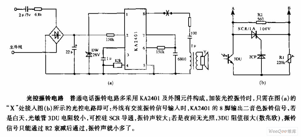
The average telephone ring circuit consists of the KA2401 integrated circuit and its associated peripheral components. To integrate a light-operated ring circuit, connect the designated part X in the provided diagram (picture a) to the light-operated circuit shown in...
The motion sensor switch circuit is a motion sensor-controlled automatic water sprinkler, but an alarm or light function can be easily added as well. The motion sensor switch circuit utilizes a passive infrared (PIR) sensor to detect motion within...
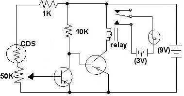
This circuit was submitted by Adam from Canada who is still at school. I have provided the text. The two transistors are used as a direct coupled switch, Adam used 2SC711 but any general purpose transistor will do e.g....
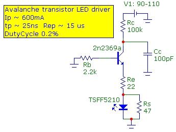
The speed of light has been measured using various methods. This note describes a method that is conceptually easy to understand and relatively simple to implement. The technique utilizes the time-of-flight optical pulse delay method, employing a short (20...
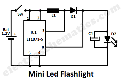
This LED lamp circuit can be utilized as a mini LED flashlight. When paired with a 1.2 V rechargeable battery, all components can be housed within a compact enclosure. The mini LED flashlight circuit typically consists of several key components:...
The circuit below is a simple dimmer circuit. A network consisting of R1, R2, VR1, C2, C3, and Q1 controls the triggering angle of the triac by adjusting the variable resistor VR1. The described dimmer circuit employs a TRIAC (Q1)...