
Flickering LED Candle using Tiny45

The flickering LED candle project aims to simulate the warm glow and flicker of a real candle using electronic components, providing a safe alternative to traditional candles. The essential components for this project typically include a microcontroller (such as an Arduino), an LED (preferably warm white or yellow), a resistor, a power source (like batteries), and a small breadboard or PCB for assembly.
The microcontroller serves as the heart of the project, controlling the LED's brightness and flickering effect through pulse-width modulation (PWM). The LED is connected in series with a resistor to limit the current and prevent damage. The power source can be a battery pack, ensuring portability and ease of use.
To create the flickering effect, the microcontroller is programmed to vary the LED's intensity in a manner that mimics the natural flicker of a candle flame. This can be achieved by randomly adjusting the brightness level at short intervals, using a combination of analogWrite functions (for PWM control) and random number generation to create an unpredictable flickering pattern.
The assembly of the circuit involves connecting the LED and resistor to the microcontroller's output pin, while the power source is connected to the microcontroller's power input. Proper soldering or breadboarding techniques should be employed to ensure reliable connections.
Safety considerations include ensuring that the circuit operates at low voltage and current levels to prevent overheating and potential hazards. The final product can be housed in a decorative holder that resembles a traditional candle, enhancing the aesthetic appeal while maintaining the functional safety of an LED-based light source.There are numerous posts on Instructables about how to make a flickering LED candle. This is my version. The project requires the following components. 🔗 External reference
Related Circuits

Here's a metal detector circuit that frequencies of the two oscillators are then mixed in similar fashion to BFO, to produce an audible heterodyne. On the surface of it, this design would seem to represent little more than a...

The circuit presented is an integrated circuit (IC) controlled emergency light. Its key features include automatic activation of the light during mains failure and a battery charger equipped with overcharge protection. In the absence of mains power, relay RL2...
This decibel meter circuit responds to sound pressure levels ranging from approximately 60 to 70 dB (decibels). The sound is captured by an 8-ohm speaker and amplified using a transistor stage along with an LM324 operational amplifier section. A...

This project demonstrates a computer control interface using a USB board (USB Interface Project). This tutorial provides a straightforward method to control devices such as LEDs, motors, and other components via a computer using a USB board. Traditionally, devices...
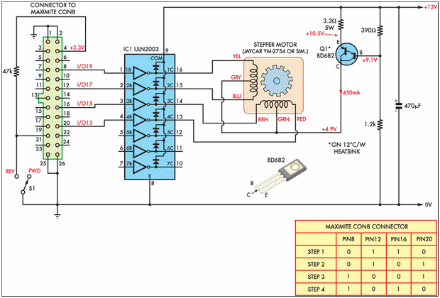
Designing and implementing this circuit was an exciting endeavor. The design of the interface involved learning how to control a device from a computer. A parallel port cable was utilized for this purpose, enabling instant control of the stepper...

This schematic illustrates the placement of a decoupling capacitor on the right side, which should be positioned as close as possible to the power pins of the microcontroller. It includes a crystal oscillator, which is optional; an internal RC...