
Decibels Meter Circuit Using LM324
The decibel meter circuit is designed to provide a visual indication of sound levels, making it useful for various audio applications. The core components include an 8-ohm speaker, which acts as a sound sensor, and the LM324 operational amplifier, which amplifies the detected audio signal. The circuit's sensitivity is adjustable, allowing for calibration based on the specific environment or application.
The use of voltage comparators within the LM324 allows for a straightforward method of determining sound level thresholds. As sound levels fluctuate, the capacitive coupling ensures that the circuit responds dynamically, charging and discharging to reflect changes in volume. The inclusion of indicator lamps provides immediate feedback, facilitating quick visual assessment of sound levels.
For optimal performance, the power supply must be stable and well-filtered. This is critical as fluctuations in supply voltage can lead to inaccurate readings. The specified filter capacitor values ensure that the circuit operates reliably, mitigating the effects of noise and ripple from the power source.
Overall, the decibel meter circuit is an effective tool for monitoring sound levels, suitable for use in environments where sound pressure levels need to be controlled or analyzed. Its design allows for flexibility in application, with the potential for further modifications to enhance functionality or adapt to specific user requirements.This decibels meter circuit responds for sound pressure levels from about 60-70 dB(Decibels). That sound is picked up by an 8 ohm speaker, amplified with a transistors stage and LM324 op-amp section. For audio signal input source, a dynamic microphone can be used but a small speaker was more sensitive.
The remaining three sections of the IC LM324 quad op-amp are used as volts comparators and drive three indicator LEDs or incandescents which are spaced about 3dB apart. An additional transistor is needed for incandescent lights as shown with the lower lamp. I used 12 volt, 50mA lamps. Each light represents about a 3dB change in sound level so that when all 3 lights are on, the sound level is about 4 times greater than the level needed to light one lamp.
The sensitivity can be adjusted with the 500K pot so that one lamp comes on with a reference sound level. The other two lamps will then indicate about a 2X and 4X increase in volume. In operation, with no input, the DC voltage at pins 1, 2 and 3 of the op-amp will be about 4 volts, and the voltage on the (+) inputs to the 3 comparators (pins 5, 10, 12) will be about a half volt less due to the 1N914 diode drop.
The voltage on the (-) comparator inputs will be around 5. 1 and 6. 5 which is set by the 560 and 750 ohm resistors. When an audio signal is present, the 10uF capacitor connected to the diode will charge toward the peak audio level at the op-amp output at pin 1. As the volume increases, the DC voltage on the capacitor and also (+) comparator inputs will increase and the lamp will turn on when the (+) input goes above the (-) input.
As the volume decreases, the capacitor discharges through the parallel 100K resistor and the lamps go out. You can change the response time with a larger or smaller capacitor. This decibels meter circuit requires a well filtered power source, it will respond to very small changes in supply voltage, so you probably will need a large filter capacitor connected directly to the 330 ohm resistor.
I managed to get it to work with an unregulated wall transformer power source, but I had to use 4700uF. It worked well on a regulated supply with only 1000uF. 🔗 External reference
Related Circuits
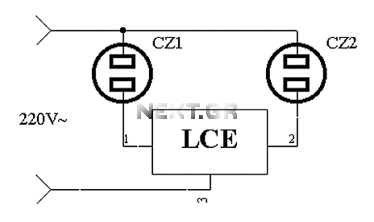
The application circuit operates the device as illustrated below. It is designed for cooling electrical equipment, typically utilizing a cooling fan to dissipate heat. The LCE employs a synchronous control socket on the device and its connections remain unchanged....
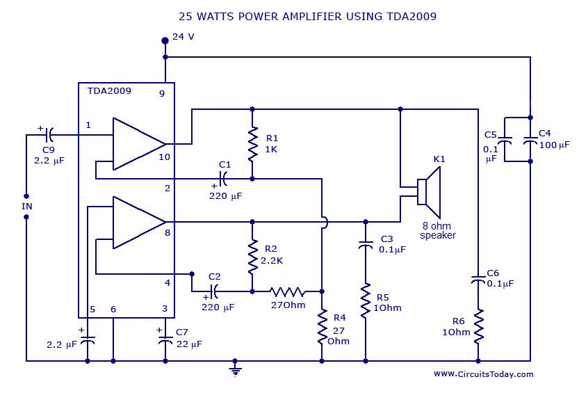
Power amplifier circuit diagram with schematics. This simple audio power amplifier circuit is designed for 25 watts output power using TDA 2009 IC, which has two channels (stereo), 12.5 W for each channel. The described power amplifier circuit utilizes the...
This simple and inexpensive circuit built around a popular CMOS hex inverter IC CD4069UB offers four sequential switching outputs that may be used to control 200 LEDs (50 LEDs per channel), driven directly from mains supply. Input supply of...

When switches SW1, SW2, or SW3 are open, the input sensitivity is optimized for high-output devices such as CD players, tuners, tape recorders, iPods, miniDisc players, and computer audio outputs. The 750 Ohm value for resistors R3, R13, and...
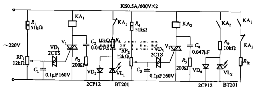
Bidirectional thyristor control. By adjusting potentiometers RPi and RPz, the lower and upper limit values can be changed. LEDs VLi and VL2 serve as indicators for low pressure and high pressure, respectively. The circuit utilizes a bidirectional thyristor to control...
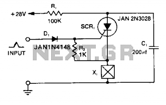
Capacitor C1 is charged to +28 V through resistor R1 and stores energy for firing the squib. A positive pulse of 1 mA applied to the gate of SCR1 will cause it to conduct, discharging C1 into the squib...