
Flow DC solenoid circuit operation

The operation of the AC solenoid in a DC circuit is based on the principles of electromagnetic induction and the characteristics of AC and DC currents. An AC solenoid is designed to operate with alternating current, utilizing the alternating magnetic field to actuate the solenoid's plunger. In contrast, when used in a DC circuit, the solenoid must be carefully managed to prevent overheating and ensure reliable operation.
The circuit typically includes a solenoid coil, which is connected to an AC power source. A capacitor (C) is included in the circuit to improve the power factor and stabilize the voltage across the solenoid. The capacitance value is crucial, as it affects the timing and response of the solenoid. Values between 1-10 µF are standard, with higher capacitance values providing smoother operation under varying load conditions.
Additionally, a current limiting resistor (R) is incorporated to protect the solenoid from excessive current that could lead to damage. The resistor value is selected based on the solenoid's specifications and the voltage supply, with a typical range of 3-12 Ω, ensuring that the solenoid operates within its rated current limits.
In practical applications, this configuration allows for the integration of AC solenoids in systems where DC control is necessary, enabling versatility in automation and control systems. Proper selection of components and careful circuit design are essential to ensure reliable operation and longevity of the solenoid in both AC and DC applications.AC solenoid DC circuit operation DC operation AC contactor circuit on the same principle, but the AC solenoid pull circuit as shown in FIG. Capacitance C- generally from 1-lOy, F (minority 20f) cF), 400V, current limiting resistor R- like to 3-12tl (minority 30fl).
Related Circuits

This is a circuit design for an FSK demodulator, which is an electronic device that converts an FSK signal into a serial digital signal. FSK modulation is used to transmit digital serial data, and demodulation is necessary to retrieve...
This is a single-channel (on/off) universal switch that can be used with any infrared remote control operating within wavelengths of 850-950 nm. The single-channel universal switch functions as a simple on/off control mechanism, allowing users to operate electronic devices remotely...
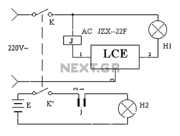
The application circuit operates the device as illustrated below, allowing for intermittent lighting in specific situations (e.g., during surgery). It utilizes an LCE module for blackout emergency lighting, which activates automatically after a power failure, ensuring uninterrupted illumination. In...

These metal detector circuit diagram is based on the TDA0161 monolithic integrated circuit, designed for metallic body detection by detecting the variations in high frequency Eddy current losses. For detecting metals, TDA0161 require an external LC tuned circuit. Output signal...

The following circuit is a power amplifier circuit for an FM transmitter with an output power of 30 watts. The power amplifier circuit utilizes a power transistor of type 2SC1946A. The FM transmitter operates with a 13.8-volt DC power...
The electronic motor speed controller circuit includes a wireless remote control transmitter circuit and a wireless remote control receiver circuit, as illustrated in the accompanying chart. The wireless remote control transmitter circuit comprises a micro-power wireless remote control transmitter...