
fsk demodulator circuit using lm565

The FSK demodulator circuit primarily employs the LM565 integrated circuit, which is a phase-locked loop (PLL) designed specifically for frequency demodulation. The operation of the LM565 involves comparing the input FSK signal with a reference frequency to produce a voltage output that is proportional to the frequency deviation of the incoming signal.
The circuit is configured to handle mark and space frequencies of 2225 Hz and 2025 Hz respectively, which are standard frequencies for certain telecommunication protocols. The demodulator effectively extracts the binary data encoded in the FSK signal by detecting the frequency shifts that correspond to the logic levels of the transmitted data.
The input stage of the circuit typically includes a band-pass filter to isolate the FSK signal from noise and other unwanted frequencies. Following this, the LM565 processes the filtered signal, and its output is a clean digital representation of the original serial data. The output can be interfaced with microcontrollers or other digital processing units for further data handling or display.
In summary, this FSK demodulator circuit is essential for applications requiring the conversion of frequency-shifted signals back into a digital format, ensuring compatibility with various communication standards. The design is particularly useful in telecommunication systems that utilize frequency-shift keying for data transmission.This is a design circuit for the FSK demodulator, that is the electronics device that converts the FSK signal to serial digital signal. To transmit digital serial data we use FSK modulation and to get back the digital data at the receiver, we need to demodulate it.
This is the figure of the circuit; The main component of this circuit is LM565. For mark /space coding, this demodulator circuit uses 2225/2025Hz. This frequency is the answering frequency of BELL113, 108, and 103 standards. [Circuit diagram source: National Semiconductor Application Notes] 🔗 External reference
Related Circuits
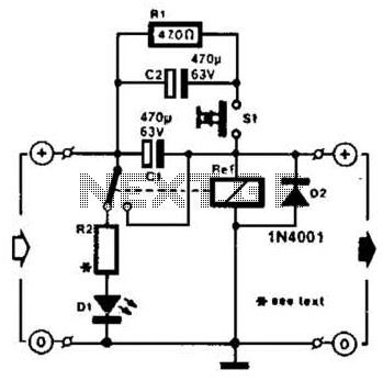
A method of adding overload protection to a power supply using a relay is shown. In each circuit, the relay must be reset by a momentary switch using a charge on capacitor C2. This prevents overload if the short...
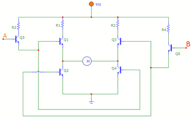
The transistors Q1, Q2, Q3, and Q4 form a bridge circuit. These are typically power transistors designed to handle high current. Transistors Q5 and Q6 drive the bridge. When input A is set high and input B is set...
The internal disconnection circuit for a blanket operates on the principle of induction. It includes a wire approximately 2 cm in length that senses the proximity of a charged mains power source. When the sensing wire is close to...
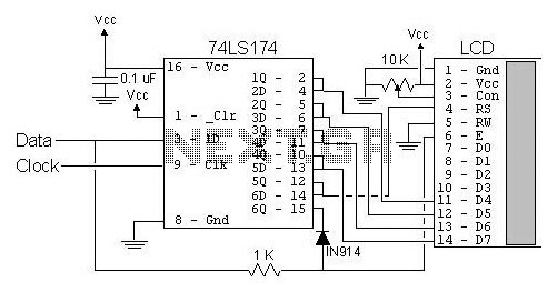
The most popular LCD interface is the Hitachi 44780 based LCD controller chip which provides a fairly easy to work with interface and low power consumption. The major drawback of the interface is the perceived complexity of working with...
The circuit is designed to deliver a surge current of 12 amps, offering performance that meets or surpasses that of typical commercial units. Additionally, it incorporates a current limiting feature, providing a level of reliability that is superior to...
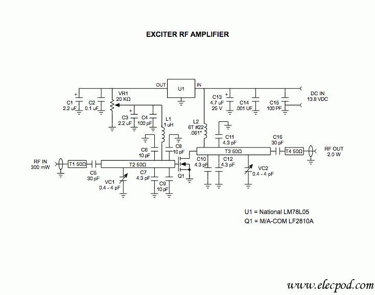
Figure A illustrates the schematic of a microstrip single-stage RF amplifier. This amplifier utilizes the M/A-Com LF2810A MOSFET, which is rated for 10 watts and operates at 28 volts, but it delivers sufficient gain for this application at a...