
Two way intercom circuit diagram using transistors and UM66 as ringer

This intercom circuit utilizes transistors to facilitate communication between two or more stations without the need for complex switching mechanisms. The design typically consists of a transmitter and a receiver unit, where each unit is equipped with a transistor amplifier to enhance audio signals.
The circuit operates by converting the audio input from a microphone into an electrical signal, which is then amplified by the transistor. The amplified signal is transmitted through the wiring to the receiving unit, where another transistor amplifies the signal further before it is output through a speaker.
Key components of the circuit include:
1. **Transistors**: These serve as the main amplifying devices and are crucial for boosting the audio signals for clear communication.
2. **Microphone**: A standard electret or dynamic microphone can be used to capture the user's voice.
3. **Speaker**: A small speaker or piezo buzzer is employed to reproduce the audio signal at the receiving end.
4. **Resistors and Capacitors**: These passive components are used for biasing the transistors, filtering, and ensuring stability in the circuit operation.
5. **Power Supply**: A simple DC power supply (typically 9V or 12V) is required to power the circuit.
The simplicity of this intercom circuit makes it an excellent choice for basic communication needs, such as in homes or small offices. Its reliance on transistors allows for a compact design, making it easier to integrate into various environments without the need for extensive wiring or additional switching components. This circuit can also be modified or expanded by adding more units, allowing for multi-station communication.A very simple intercom circuit designed based on transistors. No need for a changeover switch and you can use it just like a telephone.. 🔗 External reference
Related Circuits
A simple transistor generator and transformer converts a 1.5V battery voltage to several hundred volts. This high voltage current then passes through a diode, which rectifies the current to DC. This DC current is stored in a relatively large...
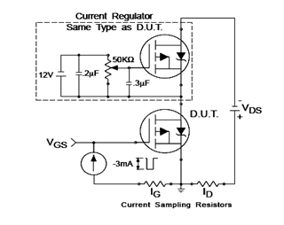
The IRF9540N Gate Charge Test Circuit is illustrated in the diagram below. The IRF9540N is recognized as a rectifier device that employs advanced processing techniques to attain an exceptionally low on-resistance per unit area, as stated in the datasheet....
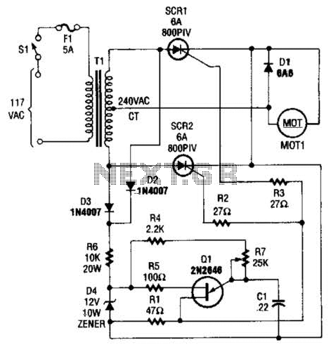
The speed-control switch provides effective control and stability across its entire operating range. This circuit utilizes two SCR devices arranged in a full-wave configuration to manage the DC power supplied to a motor. A center-tapped transformer is employed to...

The LT6552 is a video difference amplifier optimized for low voltage single supply operation. The LT6552 features a 75MHz 3dB bandwidth, a 600V/µs slew rate, and ±70mA output current, making it ideal for driving cables directly. This circuit maps...

This design circuit is for a tone/frequency detector (decoder) that can detect the presence of a signal with a specific tone. The output of the circuit will be active if the signal matches the tone of an internal oscillator....
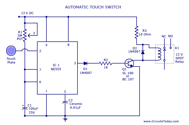
A touch switch circuit schematic utilizing a 555 integrated circuit (IC). When the touch plate is activated, a relay is switched ON for a predetermined duration, which can also be adjusted. The touch switch circuit employs a 555 timer IC...