
Fluorescent Tube Light Circuit

The fluorescent tube light circuit described utilizes a basic inverter design that incorporates a single transistor and a transformer to drive the lamp. The inverter operates by converting direct current (DC) into alternating current (AC), which is necessary for the operation of fluorescent tubes.
In this circuit, the transistor acts as a switch, controlling the flow of current through the primary winding of the transformer. When the transistor is turned on, current flows through the primary winding, creating a magnetic field in the transformer. This magnetic field induces a voltage in the secondary winding, which is connected to the fluorescent tube. The oscillation of the transistor can be achieved through feedback mechanisms, often utilizing a resistor and capacitor to establish a resonant circuit that enables the inverter to operate efficiently.
The design can be adapted to different power ratings and fluorescent tube sizes by selecting appropriate values for the transformer and the transistor. Additionally, safety features such as fuses or current-limiting resistors may be included to protect the circuit from overload conditions. This inverter circuit is known for its simplicity and cost-effectiveness, making it suitable for various applications where fluorescent lighting is required.
Overall, the implementation of a single transistor and transformer in the inverter circuit provides a compact solution for driving fluorescent tube lights, allowing for easy integration into existing lighting systems.Fluorescent Tube Light Circuit of an inverter that uses a single transistor and a single transformer. This type inverter can be made in various.. 🔗 External reference
Related Circuits
Assistance is needed in analyzing a circuit, specifically regarding the frequency cut-off between the bass and treble channels. The potential cut-off frequencies under consideration are 500Hz, 1KHz, or 5KHz. In audio processing circuits, the frequency cut-off point between bass and...
This page is provided to the domain owner free by Sedo's Domain Parking. Disclaimer: The domain owner and Sedo maintain no relationship with third-party advertisers. References to any specific service or trademark are not controlled by Sedo or the...
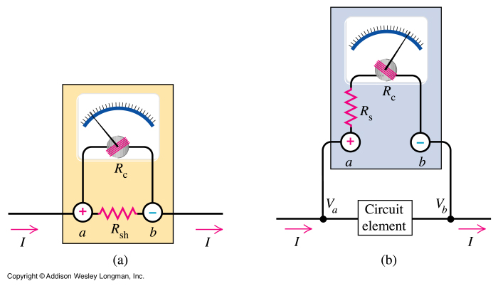
Electron trajectories in a conductor are depicted in the diagrams below. When no electric field is present inside a conducting material, electrons move randomly. However, when an electric field is applied, the electric force F = qE induces a...
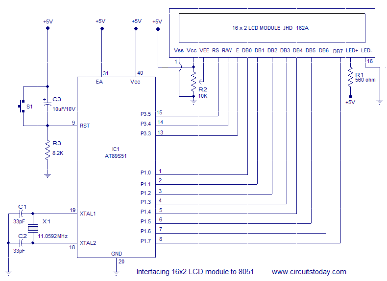
Interfacing a 16x2 alphanumeric LCD module with the AT89S51 microcontroller. The circuit diagram, theory, and program are included. JHD162 LCD module pinout and commands are provided. The integration of a 16x2 alphanumeric LCD module with the AT89S51 microcontroller involves several...
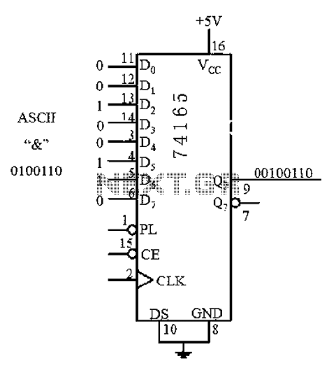
An 8 parallel input/serial output interface circuit. An 8 parallel input/serial output interface circuit is designed to convert multiple parallel data inputs into a single serial output stream. This type of circuit is commonly used in digital systems where data...

This tremolo effect circuit utilizes the XR2206 and the TCA730 integrated circuits, which are designed as an electronic balance and volume regulator with frequency correction. The tremolo effect circuit operates by modulating the amplitude of an audio signal, creating a...