
Fluorescent Tube Power Supply Circuit

The circuit employs a 2N3055 transistor configured as an oscillator, which is a common approach in power supply applications. The 2N3055 is a robust NPN power transistor capable of handling significant current and voltage levels, making it suitable for driving a transformer. In this design, the oscillator generates a high-frequency signal that is used to excite the transformer.
The transformer itself is custom-built, utilizing a Vk ferrite rod as the core material. Ferrite rods are advantageous in high-frequency applications due to their low losses and high magnetic permeability. The winding configuration of the transformer can be optimized to match the desired output characteristics for the fluorescent tube.
S2 functions as a filament switch, allowing for control over the filament power supply. While it provides convenience for switching the circuit on and off, it is noted that this component can be omitted if the application does not require independent control of the filament.
The system is designed to operate at a supply voltage of 12 V, which is a common voltage level for low-power applications. The recommendation of a 20-W fluorescent tube indicates the intended load for the circuit, suggesting that the design must accommodate the necessary current and voltage requirements to ensure proper operation of the tube.
In summary, this schematic provides a straightforward approach to building a fluorescent lamp driver using a 2N3055 transistor and a homemade transformer, suitable for applications requiring efficient power conversion and control. A 2N3055 oscillator (Ql) drives a homemade transformer, wound on a Vk, ferrite rod. S2 is used as a filament switch and it can be eliminated, if desired. A 20-W fluorescent tube is recommended. The supply is 12 V.
Related Circuits

A basic LED driver circuit consists of a 5-volt power source, a 2 kΩ potentiometer, and an LED. The LED is forward biased, with the manufacturer specifying a maximum current rating of 20 mA at a diode voltage drop...

This circuit is simple and inexpensive, which is its primary advantage. Although the output power is not high, the audio quality is good due to the TDA1910's low noise characteristics. This circuit is suitable for use as a student...
The LM2876 audio power amplifier circuit can be designed as a simple, high-efficiency audio amplifier capable of delivering 40W of continuous average power to an 8-ohm load with a total harmonic distortion plus noise (THD+N) of 0.1% from 20Hz...
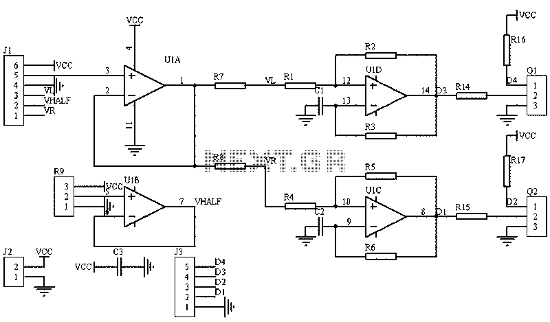
The image illustrates a circuit that utilizes a linear potentiometer (or linear Hall element) to control the PWM generation for two chassis drive motors in a gamepad or joystick used in model aircraft. J1 represents the handle of the...
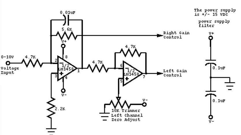
This circuit converts a mono audio signal into a stereo signal that can be panned between the left and right channels using a 0-10V control signal. It is designed for analog synthesizer systems. The circuit operates by taking a single...
The AD650 is a voltage-to-frequency (V/F) and frequency-to-voltage (F/V) converter that offers high-frequency operation and low nonlinearity, features that were previously unavailable in a monolithic form. Its inherent monotonicity in the V/F transfer function makes the AD650 suitable for...