
Mono to Stereo Audio Signal Circuit Converter

The circuit operates by taking a single mono audio input and splitting it into two outputs, corresponding to the left and right audio channels. The panning effect is achieved through the manipulation of the audio signal levels based on the control voltage input, which ranges from 0 to 10 volts.
When the control voltage is at 0V, the entire audio signal is directed to the left channel, resulting in a fully left-panned output. As the control voltage increases towards 5V, the audio signal is evenly distributed between the left and right channels, creating a centered sound. When the control voltage reaches 10V, the audio signal is fully directed to the right channel.
The circuit may utilize operational amplifiers (op-amps) to ensure that the audio signals maintain high fidelity and low distortion throughout the panning process. The design may include resistors and capacitors that set the gain and frequency response of the audio signals, ensuring compatibility with various synthesizer outputs.
Additionally, the control voltage can be generated by various sources, such as a voltage-controlled oscillator (VCO) or a control voltage sequencer, allowing for dynamic and expressive sound manipulation in real-time. This functionality makes the circuit particularly useful for sound designers and musicians seeking to enhance their audio creations with spatial effects.
Overall, this mono-to-stereo conversion and panning circuit is a valuable component in analog synthesizer systems, providing versatility and creative potential for audio engineering applications.This circuit is used to convert a mono audio signal into a stereo signal that can be panned between the left and right channel by a 0-10V control signal, it is intended for analog synthesizer systems. 🔗 External reference
Related Circuits
Sometimes, for a variety of reasons, it would be nice to vary the width of the sound stage when listening to stereo recordings. Although technically this is anything but hi-fi, it is a useful addition to PC speakers, or...
A frequency synthesizer circuit diagram has been found, but clarification is needed regarding a component connected to VDD from pin 9, VSS from pin 8, and pin 12, which is linked to the phase comparator 2. The component in...
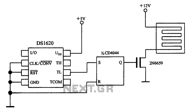
The circuit involves a smart temperature control system utilizing DS1620 temperature sensors with a three-wire serial interface for managing a small electric heater. When the CD4044 type RS flip-flop is set to 1, the output Q becomes high, which...
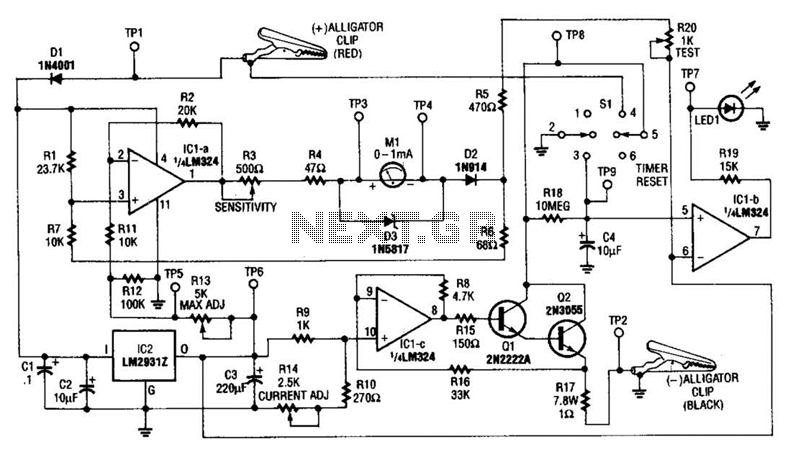
This circuit measures the cold cranking amps of a battery by discharging the surface charge and then assessing the internal resistance. This method provides a more accurate measurement than merely observing the instantaneous voltage drop under load. A constant-current...
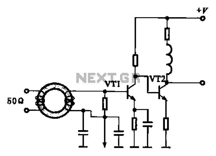
A broadband high-frequency amplifying circuit is primarily composed of a high-frequency matching transformer and an amplifying transistor. This circuit is designed to handle large high-frequency signals. The input of the amplifier circuit utilizes a matching transformer to ensure that...
A diesel tractor is equipped with a magnetic reed switch in the fuel tank to indicate low fuel levels. The switch remains open when fuel is present in the tank and closes when the fuel level drops below a...