
fm am mw sw antenna amplifier

The FM, AM/MW, and SW antenna amplifier circuit serves to significantly boost the sensitivity of radio receivers operating within these frequency bands. The core component of this circuit, the MPF 102 transistor, functions as a high-frequency amplifier, providing the necessary gain to weak incoming radio signals. The choice of substitute transistors, such as the NTE 451 or 2N4406, ensures flexibility in sourcing components while maintaining circuit functionality.
The inductor L1 plays a crucial role in tuning the circuit to the desired frequency range. The 470 µH coil is specifically designed for AM applications, allowing it to effectively filter and amplify signals in that band. Conversely, the 20 µH coil is tailored for shortwave applications, optimizing performance for higher frequency signals.
Powering the circuit with a 9V alkaline battery is straightforward; however, for those utilizing an external power supply, the inclusion of a 0.04 µF capacitor is essential. This capacitor acts as a bypass, filtering out unwanted noise that could interfere with the amplifier's performance, thereby ensuring a cleaner signal output.
The antenna design is flexible, with options for an 18-inch telescope or a thick copper wire. This flexibility allows users to adapt the circuit to their specific needs and environment, enhancing the overall effectiveness of the antenna amplifier. The simplicity of the circuit design, combined with the use of readily available components, makes this antenna amplifier an accessible solution for improving radio reception across various bands.Here is a schematic of FM, AM/MW and SW antenna amplifier circuit or we can also say it antenna preamplifier circuit which can be used to increase the faint signals of FM, AM/MW & SW bands. The circuit is very simple and easy to build using only one transistor MPF 102 and few other components.
But if you didn`t found MPF 102 transistor then you ca n use NTE 451 or 2N4406 as substitutes. For L1 use 470uH coil for AM and for shortwave use 20uH coil. This circuit can be powered with a 9V alkaline battery or if you are using power supply then bypass power supply with a 0. 04 uF capacitor to decrease noise. Antenna can be a 18 inch telescope or 18 inch thick piece of copper wire. 🔗 External reference
Related Circuits
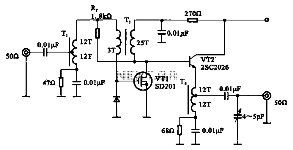
A broadband amplifier circuit utilizing a negative feedback amplifier configuration is presented. This circuit employs transformer coupling and a combination of amplifying sections and field-effect transistors (FETs). The input signal is applied to the center tap of the transformer...
This amplifier features high fidelity (Hi-Fi), high sensitivity, low power consumption, and low distortion, making it an excellent choice for high fidelity sound systems. The process of creating a printed circuit board (PCB) can be accomplished in a few...
This article discusses several opamp-based headphone amplifier circuits, including suggestions for selecting opamps, input coupling and filtering, high current output stages and power supply options. There are no recommendations for specific opamp brands or models. For tube devotees, there...
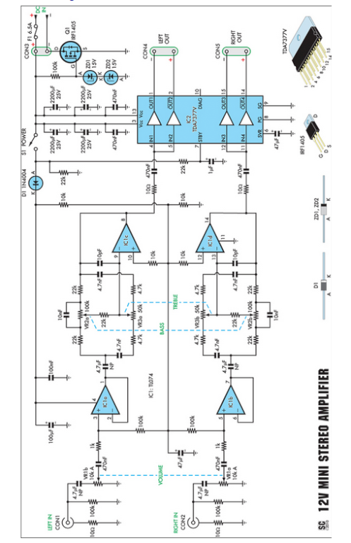
Amplifiers that operate on 12V DC typically do not deliver significant power and are often not classified as high-fidelity (hifi) devices. However, this compact stereo amplifier meets the power requirements effectively. This compact stereo amplifier is designed to operate efficiently...
The schematic illustrates a 12 W Bridge Amplifier circuit diagram utilizing the TDA2007A, a class AB dual audio power amplifier. This amplifier is specifically designed for stereo applications in music centers, television receivers, and portable radios. As stated in...
Amplifying weak radio signals presents the challenge of also amplifying noise. The ability to receive signals is contingent on the level of background noise, which can include man-made interference or static. In this design, the RF signal first encounters...