
Stereo 12W Bridge Amplifier Circuit TDA2007A

The 12 W Bridge Amplifier circuit is configured to maximize audio output while maintaining sound quality. The TDA2007A operates in a class AB configuration, which combines the efficiency of class B operation with the linearity of class A, resulting in reduced distortion and improved fidelity. This amplifier is capable of delivering up to 12 watts of output power into an 8-ohm load, making it suitable for driving small speakers in various audio applications.
The circuit design incorporates input and feedback resistors to set the gain of the amplifier, ensuring that the output signal is appropriately amplified for the intended application. Capacitors are strategically placed for coupling and decoupling purposes, allowing for the effective transmission of audio signals while filtering out unwanted noise and DC offsets.
Additionally, the TDA2007A features built-in protection mechanisms, including AC short circuit protection, which guards against potential damage caused by short circuits on the output. Thermal overload protection is also integrated, preventing the amplifier from overheating during prolonged use or under heavy load conditions. This enhances the reliability and longevity of the circuit in real-world applications.
Overall, the 12 W Bridge Amplifier circuit using the TDA2007A exemplifies a robust solution for audio amplification needs, combining performance, protection features, and design simplicity, making it an excellent choice for consumer electronics.The following schematic shows 12 W Bridge Amplifier circuit diagram as an application of the TDA2007A a class AB dual audio power amplifier which is designed for stereo application in music centers, TV receivers and portable radios. According to the datasheet, this TDA2007A has features such high output power, high current capability, AC short circuit protection, and thermal overload.
🔗 External reference
Related Circuits
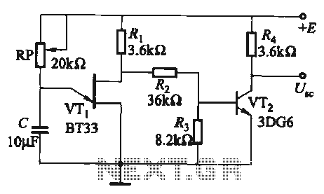
The circuit comprises a single-junction transistor VTi, a resistance Ri, a potentiometer RP, and a capacitor C, forming a relaxation oscillator and an amplifier transistor VTz. The adjustment potentiometer RP allows for changing the relaxation oscillation frequency, providing a...
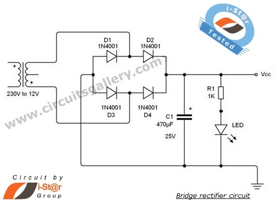
A rectifier is an electronic circuit that converts AC voltage to DC voltage. It can be implemented using a combination of capacitors and diodes. The unique property of diodes, which allows current to flow in a single direction, is...
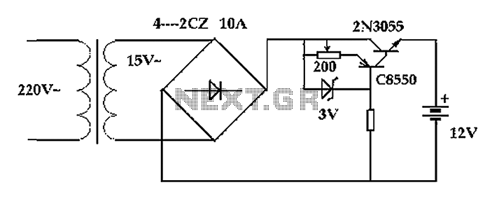
The circuit operates after a transformer, utilizing a bridge rectifier and conditioning for battery charging. The charging current transformer can be easily adjusted to provide approximately 12V at 100Ah battery charging. The required charging current is 10A, and a...
This is a fun and non-dangerous project for those people who like to throw projectiles magnetically. It simply works by placing a ferromagnetic projectile at one end of a coil and pulsing some power in it. The trick is...
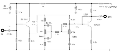
The first BC109C transistor functions as a buffer, delivering a high input impedance of approximately 250k and exhibiting a voltage gain marginally below unity. Given that the Baxendall tone control circuit operates passively, it attenuates all audio frequencies. The...
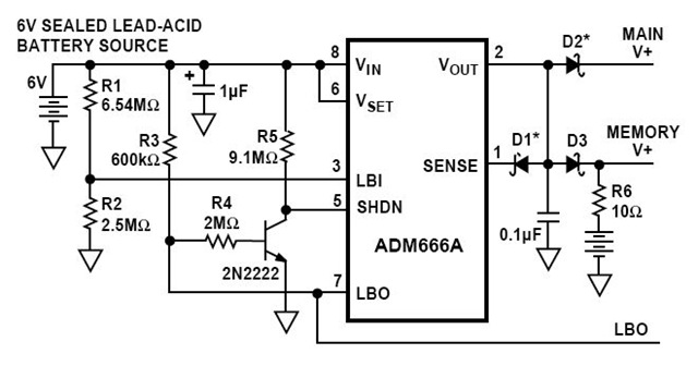
This is a circuit diagram for a solid-state charge detector. It can detect very weak electric fields. The circuit has three components: a 6-volt battery, a light-emitting diode (LED), and a field-effect IC ADM666A. The solid-state charge detector circuit is...