
FM Booster~Active FM Antenna Amplifier

The FM booster circuit is designed to enhance the reception of FM signals from distant stations by amplifying weak radio frequency signals. The primary component of this circuit is the VHF/UHF transistor 2SC2570, which operates in a common-emitter configuration. This configuration is advantageous for RF amplification as it provides a good balance of gain and bandwidth.
The circuit typically includes several key components: an input matching network, a tuned circuit for frequency selection, and a power supply circuit. The input matching network is designed to optimize the impedance seen by the antenna to maximize signal capture. The tuned circuit, often consisting of an inductor and a variable capacitor, allows for selective amplification of the desired FM frequency while filtering out unwanted signals.
Power supply requirements for the 2SC2570 transistor should be carefully considered, as it operates efficiently within a specific voltage range. The circuit may also incorporate bypass capacitors to stabilize the power supply and improve performance by reducing noise.
Additionally, it is essential to ensure proper grounding and shielding of the circuit to minimize interference from external sources. The layout should be compact to reduce losses and maintain signal integrity. The output of the amplifier can be connected directly to an FM receiver or a further processing stage, depending on the application.
Overall, the FM booster circuit utilizing the 2SC2570 transistor is a robust solution for improving FM radio reception, particularly in areas with weak signal strength.FM Booster, Active FM Antenna Amplifier This FM booster that can be used to listen to programmes from distant FM stations clearly. The circuit comprises a common-emitter tuned RF preamplifier wired around VHF/UHF transistor 2SC2570.
(Only C.. 🔗 External reference
Related Circuits
More: The input data lacks specific content, providing only placeholders without any detailed information. In the context of electronic schematics, a comprehensive description typically involves detailing the components, their interconnections, and the overall functionality of the circuit....
Antennas that are much shorter than 1/4 wavelength present a very small and highly relative impedance that is dependent on the received frequency. It is difficult to match impedances over a decade of frequency coverage. Instead, input stage Q1...
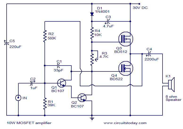
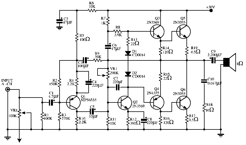
This article lists various types of audio amplifier circuits using MOSFETs. All circuits have been tested in a laboratory environment and have shown satisfactory performance. The amplifier utilizes one transistor, two MOSFETs, and a few resistors and capacitors in...
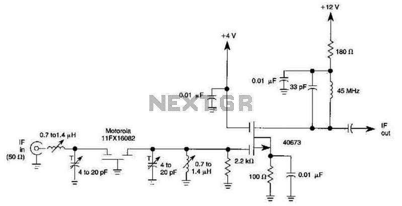
A 40673 dual-gate MOSFET is matched to a crystal filter operating at 45 MHz. The filter impedance is approximately 2 kΩ. The +4 V source can be adjusted to control the gain, ranging from +4 V to -4 V. The...
The primary component of this circuit is the LM386 amplifier chip. It also incorporates a transistor input to buffer the input signal and provide additional gain for the LM386. This compact unit has proven useful in various scenarios, particularly...
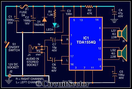
The circuit diagram illustrates a robust stereo amplifier capable of delivering 22W of power. It is based on the widely used single-chip audio power amplifier TDA1554Q (IC1), which is configured as two 22W stereo bridge amplifiers. While listening to...