
Simple FM Transmitter Circuit

The simple FM transmitter circuit utilizes a transistor to modulate audio signals onto a radio frequency carrier wave. The circuit typically consists of a few key components: a transistor, resistors, capacitors, and an inductor. The transistor acts as the main amplifying element, allowing the circuit to generate the necessary RF signal for transmission.
In operation, an audio input signal, such as from a microphone or audio player, is fed into the base of the transistor. The transistor modulates this audio signal onto a carrier frequency, which is determined by the values of the inductor and capacitor in the circuit. The output from the collector of the transistor is then coupled to an antenna, which radiates the modulated signal into the surrounding environment.
To achieve a transmission distance of approximately 300 meters, the circuit may require an appropriate power supply, typically a battery or DC power source, and the antenna must be designed to match the frequency of operation for optimal performance. The choice of components, particularly the transistor type and the values of the passive components, will significantly influence the efficiency and range of the transmitter.
Tuning the circuit can be accomplished by adjusting the variable capacitor or inductor, allowing the user to select the desired frequency for transmission. Proper shielding and layout considerations are essential to minimize interference and ensure compliance with local regulations regarding unlicensed transmission. This simple FM transmitter circuit serves as an excellent introduction to radio frequency design and modulation techniques.Simple FM Transmitter Circuit This simple FM transmitter circuit was built using a transistor with a transmission distance of about 300m around your home. It`s. 🔗 External reference
Related Circuits
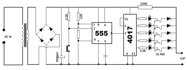
Battery eliminators are circuits that create a DC power supply from AC mains. Essentially, battery eliminator circuits consist of a step-down transformer, rectifier, and voltage regulator. A simple circuit of a multipurpose battery eliminator features various output voltage ranges...
The paraphase configuration is noteworthy for its ability to adjust either treble or bass, but not both simultaneously. The adjustments made to the tone controls directly influence the slope of the frequency response and the extent of bass and...

The circuit serves as a signal source for calibration level meters or sensor-driven differential transformers. The oscillation frequency is determined by the 74HC04, producing a frequency of 1 kHz through resistor R. The supply voltage of the circuit changes...

Currently, the use of cookers has become fashionable due to their speed, cleanliness, and low pollution levels, making them a favorite among consumers. Cookers circuit. The modern cooker circuit typically involves a combination of heating elements, control systems, and safety...
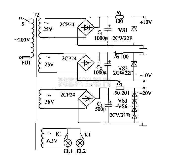
A DC power supply with a shunt, rectifier, filter, current limiting, and voltage regulation, providing 10V voltage outputs. The circuit is simple and low cost, designed to meet the requirements of various applications. Additionally, it features a 3V indicator...
Chris from PyroElectro.com has an informative article detailing a do-it-yourself radar system constructed using the PIC18F452 microcontroller. This project is an excellent hobbyist endeavor, although the schematic design is quite complex. The system integrates three primary components to form...