
FM Crystal Radio Receivers
The described circuit functions as a VHF FM receiver utilizing a crystal radio approach, leveraging the unique properties of germanium diodes for signal detection. The circuit design emphasizes the importance of antenna length and tuning for optimal performance, particularly in environments where traditional reception methods may be compromised. The use of a telescopic antenna not only aids in reception but also acts as a resonant element, enhancing the circuit's ability to capture and amplify weak signals. The inclusion of adjustable components such as trimmer capacitor C2 allows for fine-tuning, ensuring that the user can achieve the best possible audio quality from the received signals. The careful selection of diode characteristics and the configuration of the resonant tank circuit are critical to maintaining signal integrity and achieving satisfactory performance in VHF band reception. Overall, the circuit exemplifies a practical application of crystal radio technology to modern FM broadcasting, demonstrating its versatility and effectiveness in various listening conditions.The notion of "crystal radio" is strongly associated with huge antennas and radio broadcasting on long and medium bands, in this article, the author describes the experimentally tested detector circuits of VHF receivers designed to listening to a FM stations. The very possibility of receiving VHF FM detector was discovered accidentally. One day I was walking in the Terletskiy park in Moscow, Novogireevo, I decided to listen to the broadcast - I had a simple crystal set without resonant tank ( this circuit is described in the "Radio", 2001, – 1, Fig. 3 ). The receiver had a telescopic antenna with length of about 1. 4 m. Wonder whether it is possible to receive radio broadcast with this short antenna It was possible to hear, but weakly, simultaneous operation of two stations.
But what is surprised me is the volume of receiving was rise and fall periodically almost to zero after every 5. 7 m, and it was different for each radio station! It is known that in the LW and MW bands, where the wavelengths are hundreds of meters, it is impossible.
I had to stop at the point of receive with maximum volume of one of the stations and listen attentively. It turned out - this is "Radio Nostalgie", 100. 5 MHz, broadcasting from the near city Balashikha. There were no line of sight between antennas. How does the FM transmission could be received by using the AM detector Further calculations and experiments shows that it is quite possible and is not depends on the receiver.
A simple portable FM crystal receiver is made exactly the same way as an indicator of the electric field, but instead of measuring device it is necessary to connect a high-impedance headphones. It makes sense to add an adjustment of coupling between the detector circuit and the resonant tank to adjust the maximum volume and quality of the receiving signal.
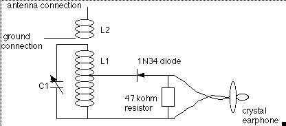
The circuit diagram of the receiver suitable for these requirements is shown in Fig. 1. This circuit is very close to the circuit of the receiver mentioned above. Only the VHF resonant tank has been added to the circuit. VD1, VD2 - GD507A - an old USSR Germanium high-frequency diodes with the capacitance of 0. 8 pF (at the reverse voltage of 5V), the recovery time of reverse resistance is no more than 0. 1 uS (at the Idirect pulse=10 mA, Ureverse pulse=20 V, Icutoff=1 mA) The device contains a telescopic antenna WA1, directly connected to the resonant tank L1C1. The antenna is also an element of the resonant tank, so to get the maximum power of the signal it must be adjust both the length of the antenna and the frequency of the tank circuit.
In some cases, especially when the length of the antenna is about 1/4 of the wavelength, it is useful to connect the antenna to a tap of the tuning coil L1 (find the suitable tap of the coil by finding the maximum volume of the signal). The coupling with the detector can be adjust by trimmer C2. Actually the detector is made of two high-frequency germanium diodes VD1 and VD2. The circuit is completely identical to the voltage doubling rectifier circuit, but the detected voltage would be doubled if only the trimmer capacitor C2 value is high, but then the load of the resonant circuit L1C1 would be excessive, and its quality factor Q will be low.
As a result, the signal voltage in the circuit tank L1C1 will be lower and the audio volume will be lower too. In our case, the capacitance of the coupling capacitor C2 is small enough and voltage doubling does not occur.
For optimal matching the detector circuit with the tank circuit the impedance of the coupling capacitor must be equal to the geometric mean between the input resistance of the detector and the resonant resistance of the tank circuit L1C1. Under this condition, the detector is getting the maximum power of the high-frequency signal, and this is corresponding to the maximum audio volume.
The capacitor C3 is shunting the higher frequencies at the output of the detector 🔗 External reference
Related Circuits
The circuitry of the Regency exhibits several unique characteristics. Notable features include the self-oscillating mixer stage, the base bias voltage of the second IF stage derived from the AF power stage, an unusual IF frequency of 262 kHz, and...
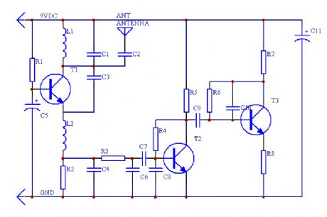
This is a simple RF receiver primarily designed for low-distance digital radio receiver applications. The analog output of this circuit should be connected to a Schmitt-trigger signal conditioning circuit with an appropriate capacitor value (from the collector of T3)....
This is highly illegal. As a consumer, compliance with Part 15 of the rules and regulations is mandatory. Part 15 stipulates that a device must accept any interference it receives and must not cause harmful interference, such as jamming...
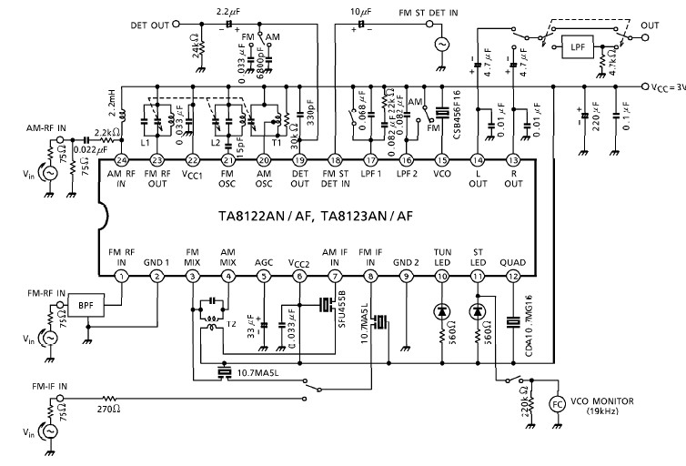
A simple low-power AM/FM radio receiver electronic project can be designed using the TA8122 integrated AM/FM receiver, manufactured by Toshiba Semiconductor. This radio receiver circuit can be utilized for portable radio applications or similar devices. The TA8122 radio receiver...
A simple audio amplifier application using a TL431 voltage regulator. The amplifier is designed to produce room-filling sound from a standard clear radio equipped with a long-wire antenna and suitable ground. The chip is similar in complexity to a...
The coil on the left is coil #1, and has 17 taps. The other coil is coil #3. The vertical strips are the lath material, screwed to the 1 foot long base. Holes drilled in the ends of the...
Warning: include(partials/cookie-banner.php): Failed to open stream: Permission denied in /var/www/html/nextgr/view-circuit.php on line 713
Warning: include(): Failed opening 'partials/cookie-banner.php' for inclusion (include_path='.:/usr/share/php') in /var/www/html/nextgr/view-circuit.php on line 713