
Selective Frequency Crystal Radio

Construction of coil #1 requires about 72 feet of #24 wire. Two holes should be punched about 1/4 inch apart close to one end of the coil form. An inch of wire should be threaded into one hole and out the other to anchor the coil. Approximately 152 turns of wire should be wound in a single, closely wound layer along the coil, with a small loop made every 10 turns, each loop about 1/4 inch in diameter. These loops will serve as taps, and staggering them so every other tap is offset by about 1 inch will create two rows of taps. After the last turn, a final tap should be made, and two more small holes should be punched as at the beginning to anchor the other end of the coil. The finished turns can be secured with cement, white glue, or tape, ensuring that the taps remain uncovered. The enamel off the taps must be removed, which can be done by burning it off with a small flame followed by lightly sanding them clean. Tinning the taps with solder is also an option. This coil will be used for an antenna tuner, hence the numerous taps.
The described circuit involves a variable tuning mechanism using two polyfilm RF tuner capacitors, which allow for fine adjustments in the circuit's resonant frequency. The arrangement of fahnestock clips facilitates easy connections for testing and troubleshooting, while the use of alligator clips allows for rapid prototyping and adjustments. The design emphasizes modularity, enabling the replacement of coils without dismantling the entire setup. The detailed construction of coil #1, with its specific winding technique and tap configuration, is crucial for achieving the desired inductance and tuning range, making it suitable for various RF applications. The careful adjustment of the trimmer capacitors ensures optimal performance across the intended frequency band, enhancing the overall functionality of the circuit.The coil on the left is coil#1, and has 17 taps. The other coil is coil #3. The vertical strips are the lath material, screwed to the 1 foot long base. Holes drilled in the ends of the lath hold the dowel rod; it can be removed to change coils. The bottle caps are the knobs of the two polyfilm rf tuner capacitors, which are stuck to the base with sticky tape. On the right of the base are screwed 3 fahnestock clips. The detector is connected between the rear clip and the right front clip. Leads with alligator clips are connected to the right rear and front left fahnestock clip, and leads and alligator clips are also connected to each capacitor.
The two front fahnestock clips are for phones. The capacitors I used have three connections. The center one is the base, and the outside ones are for the rotors of the two sections. You need to connect the two outside ones, and connect them to one lead, about 8 inches long, and connect the center connection to another lead. If you look on the back of the capacitor, you will notice two small trimmer capacitors with a screwdriver adjustment.
Adjust both these to minimum capacitance ( you will see a full circle instead of a half-moon shape); this will give you full BC band coverage when used with the coils you will wind next. Cut holes in the center of the two plastic bottle caps ,and shape them with a knife to fit snugly over the tuning shaft of the capacitors, and then hold them in place with a small washer and screw.
Use the double sided sticky tape to mount the capacitors on the base, and fasten alligator clips to the ends of the leads. To avoid working the delicate capacitor leads, I used an ordinary stapler to staple the leads to the base close to the caps.
Construction of coil #1: This takes about 72 feet of #24 wire. Using a pin, punch two holes about 1/4 inch apart close to and parallel to one end of your coil form. Thread about an inch of wire into one hole and out the other to anchor your coil. Now wind about 152 turns of wire in a single, closely wound layer along the coil; at every 10 turns (yes 10), make a small loop that sticks above the coil, each loop being about 1/4 inch in diameter - you will get the hang of this quickly.
To avoid crowding these loops, which you will use as taps, you might stagger them so every other tap is offset on the coil by about 1 inch; you will end up with two rows of taps. After the last turn, make a final tap and, use the pin to make two more small holes as you did in the beginning, and thread about an inch of wire in and out to anchor the other end of the coil.
You can use either cement or white glue to hold your finished turns onto the coil form. Tape is ok too; just don't cover the taps. Now comes the really tedious part; getting the enamel off the taps. I usually take a small flame, as from a lighter or candle, and burn the enamel off the tap, then lightly sandpaper them clean. If you like, do as I do and tin the taps with solder. This coil will eventually be used for your antenna tuner, hence all the taps. I don't draw well, so here is a link to what a tap should look like: 🔗 External reference
Related Circuits
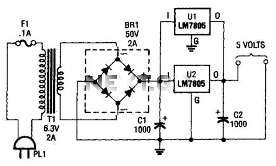
This DC supply is excellent for operating battery-powered antique radios, as it is designed to prevent damage to the tube filaments. The circuit is useful for powering the filaments of 00-A, 01-A, 112A, and 71A tubes, which require 5V...
Circuit of a crystal-controlled FM transmitter. The circuit utilizes a crystal oscillator and several power amplifier stages to enhance output power. The crystal-controlled FM transmitter circuit is designed to generate frequency-modulated signals with high stability and precision. At the core...
A simple audio amplifier application using a TL431 voltage regulator. The amplifier is designed to produce room-filling sound from a standard clear radio equipped with a long-wire antenna and suitable ground. The chip is similar in complexity to a...
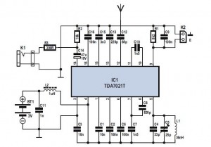
The FM Radio Receiver IC TDA 7012T is a straightforward component that offers excellent sensitivity and selectivity for FM radio reception. This single-chip FM receiver, known as IC TDA7012T, requires minimal additional components to construct an FM receiver. The...

This oscillator may contain several switched crystals to provide channelized operation. A buffer amplifier may be added if desired. The oscillator described is designed to utilize multiple switched crystals, enabling it to operate across various frequency channels. This feature is...
The variable frequency power supply is a crucial component of the power system, as its characteristics significantly impact the security and reliability of the overall system. The modern variable frequency power supply is characterized by low power consumption and...