
FM IF amplifier circuit composed of ceramic filters

The FM IF amplifier circuit operates by receiving an intermediate frequency signal at 10.7 MHz, which is a standard frequency for FM radio systems. The circuit begins with the input signal being fed into the primary winding of transformer T1, which is configured as part of a resonant circuit. This configuration allows for selective amplification of the desired frequency while attenuating others, ensuring that only the relevant signal is processed.
The ceramic filter CF1 plays a crucial role in this setup by providing a narrow bandwidth around the 10.7 MHz frequency. This filter is essential for maintaining signal integrity, as it reduces interference from adjacent channels and enhances the overall quality of the received signal. The output of the ceramic filter is then connected to the base of transistor VT1, which serves as the main amplification stage of the circuit. Transistor VT1 amplifies the selected intermediate frequency signal, increasing its amplitude for further processing.
Following amplification, the signal is passed to the secondary transformer T2, which further conditions the signal before it is sent to the next stage of the FM receiver. The use of transformers in this circuit helps in impedance matching and allows for efficient signal transfer between stages.
Overall, this circuit exemplifies a straightforward yet effective approach to FM signal amplification, leveraging ceramic filters and transformers to achieve high performance in radio frequency applications. The design considerations prioritize simplicity and reliability, making it suitable for various FM receiver implementations.It shows a ceramic filter composed of FM IF amplifier circuit, the FM intermediate frequency amplifier circuit mainly by the IF input variable voltage regulator T}, ceramic filters CF1, IF amplifier and IF transformer T2 VT1 other parts can normally be used amplifying FM IF signal. IF from the FM front-end circuitry (10.7 MHz) into the first intermediate frequency signal TJ transformer primary winding which cs composition and frequency of the resonant circuit, having a frequency selection function, Tl transformer secondary connected with a 10.7 MHz ceramic filters it will send the selected intermediate frequency signal to an intermediate frequency amplifier at the base of the transistor VT1, amplified. VT1 amplified signal and then by the second intermediate frequency transformer Tz output to the next level.
The circuit has a simple structure, good performance characteristics.
Related Circuits
This circuit utilizes the power MOSFET IRF840 for a 60-watt linear amplifier. The IRF series of power transistors are available in various voltage and current ratings. The described circuit employs the IRF840, which is a high-voltage N-channel MOSFET, suitable for...
After turning off TT2, the input signal enters through chi Az, where the input resistance is very high and reaches the same potential. The inverting input terminal must also be associated with this movement. Therefore, Trr functions as a...
A small circuit that can find a lot of applications for measuring time. It has the capability to inform with a sound signal from the BZ1. At the same time, there exists the possibility to drive an external circuit...
7W Mono Audio Amplifier Kit - This compact amplifier is designed around the TDA2003 integrated circuit, which can provide 7 watts of audio power into a 4-ohm load. The 7W Mono Audio Amplifier Kit utilizes the TDA2003 IC, a popular...
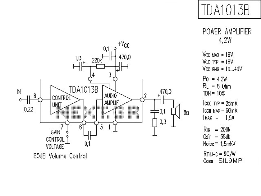
The following is a circuit for a 4-watt audio amplifier. The amplifier utilizes an integrated audio amplifier chip, TDA1013B, which is capable of delivering an audio power output of up to 4W at an 8-ohm load. Its wide supply...
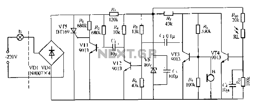
This circuit describes a sound and light control delay system for a walkway stairs light switch. It involves various components including 220V AC electric bulbs, diodes (VD1-VD4), and resistors. The circuit utilizes a rectifier regulator to stabilize the voltage...