
TDA1013B - 4W Audio Amplifier Circuit

The 4-watt audio amplifier circuit based on the TDA1013B chip is designed for efficient audio amplification in a variety of applications. The TDA1013B is a robust integrated circuit that simplifies the design process by integrating many necessary functions, including power amplification, gain control, and feedback mechanisms. The output power of 4 watts at an 8-ohm load ensures sufficient volume for most consumer audio applications.
The power supply for this amplifier can vary widely, accommodating both mains and battery sources, which enhances its versatility. The circuit is engineered to maintain performance across different power conditions, making it suitable for portable devices as well as fixed installations.
The logarithmic DC volume control allows for precise adjustment of audio levels, which is particularly beneficial in environments where sound levels need to be adjusted frequently or finely tuned. The control voltage range of 2V to 6.5V provides flexibility in integration with other control systems, such as microcontrollers or digital signal processors.
In terms of external components, the circuit is designed to minimize the number required for operation, which aids in reducing the overall footprint and complexity of the design. The stability provided by the integrated closed-loop configuration ensures consistent performance across varying loads and supply voltages, making it a reliable choice for engineers and designers.
Overall, this 4-watt audio amplifier circuit is ideal for a wide range of audio applications, offering a balance of power, efficiency, and ease of integration for both professional and consumer markets.The following a circuit of 4 watt audio amplifier. The amplifier is using on integrated audio amplifier chip, TDA1013B which is able to gained the audio power output up to 4W at 8 ohm loads. The wide supply voltage range makes this amplifier circuit ideal for applications in mains and battery-fed apparatus such as television receivers and record p
layers. This amplifier circuit can be used in a variety of applications such as car audio systems, home theater systems, personal audio systems, public address systems etc. The DC volume control stage has a logarithmic control characteristic with a range of more than 80 dB; control is by means of a DC voltage variable between 2 and 6.
5 V. The audio amplifier has a well defined open loop gain and a fixed integrated closed loop. This device requires only a few external components and offers stability and performance. 🔗 External reference
Related Circuits
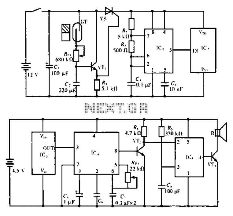
The alarm circuit is composed of two main components: the transmitter and the receiver. The transmitter circuit, as illustrated in Figure A, features a smoke break reed switch labeled GT. When a magnet approaches the GT, the internal contacts...
The baby-alert receiver consists of three transistors: Q2, configured as a high-gain linear amplifier; Q3, functioning as both an amplifier and detector; and Q4, which operates primarily as a switch. Additionally, there are several other components involved. The system...
This circuit is designed for precise measurement of temperature in degrees Celsius. It features a transmitter section that converts the output voltage from the temperature sensor, which is proportional to the measured temperature, into a frequency signal. This frequency...
A 100W RF power amplifier circuit is constructed using two BLY94 transistors. For additional RF amplifier options, refer to the list below. Components include active components. The 100W RF power amplifier circuit utilizing BLY94 transistors is designed to amplify radio...

The physical circuit layout is extremely critical. Breadboarding is not recommended. A double-sided copper-clad printed circuit board will result in more favorable system operation. The design and implementation of electronic circuits require careful consideration of the physical layout, as it...
Converting periodic waveforms to square waves is essential for extracting clock signals from data, creating waveform generators, and developing timing-pulse generators. A square-wave conversion circuit is more advantageous when the duty cycle of the square wave is variable and...