
FM modulator circuit

The FM modulator circuit operates by generating a carrier signal at a specific frequency, which is then modulated by the audio signal input. The Motorola MC1648P serves as the core component, functioning as a voltage-controlled oscillator (VCO). The frequency of the output signal is influenced by the control voltage applied to the varactors, which are semiconductor devices whose capacitance changes with the applied voltage.
In this configuration, the two MV-209 varactors are connected in a manner that allows for effective modulation of the oscillator's frequency. By adjusting the 5000 Ω potentiometer, the biasing voltage applied to the varactors can be finely tuned, ensuring that the modulation is linear across the desired frequency range. This linearity is critical in maintaining audio fidelity, as it ensures that the modulated signal accurately represents the input audio signal without introducing distortion.
The output frequency, typically centered around 100 MHz, can be modified by selecting different inductors. The inductance value directly affects the oscillation frequency of the circuit, allowing for flexibility in tuning the modulator to specific frequency allocations. This capability is particularly useful in applications such as broadcasting, where precise frequency control is necessary.
Overall, the design of the FM modulator circuit is a balance of various components working in harmony to achieve a stable and adjustable output frequency, making it suitable for a range of communication and broadcasting applications.The FM modulator circuit (frequency modulation) is built with a Motorola MC1648P oscillator. Two varactors, Motorola MV-209 are used to frequency modulate the oscillator. The 5000 ? potentiometer is used to bias the varactors for the best linearity. The output frequency of approximately 100 MHz can be adjusted by changing the value of the inductor. The ou.. 🔗 External reference
Related Circuits
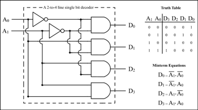
The Encoder and Decoder are different types of combinational circuits used to convert binary information to decimal, octal, and hexadecimal formats, and vice versa. A decoder is a combinational circuit that converts n-bit binary information into 2^n unique outputs....
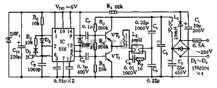
The circuit operates as an electronic ballast for fluorescent lamps, incorporating a rectifier filter circuit, a high-frequency oscillation circuit, and an output circuit. The rectifier filter circuit consists of a rectifier diode (VD1) and filter capacitors (C1, C2). The...
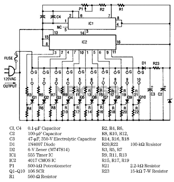
The light sequencer employs two integrated circuits (ICs) and ten silicon-controlled rectifiers (SCRs) to create an alternating current (AC) sequencer. The first IC, a 555 timer, is configured as an astable multivibrator to generate clock pulses for the second...
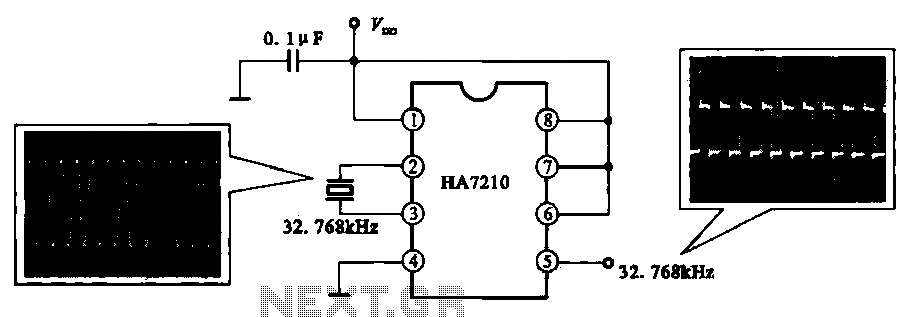
This circuit illustrates a 32.768 kHz micro-power clock oscillator, suitable for use in mobile phones, laptop computers, and home appliances. It generates a clock signal that can be utilized in various applications. The 32.768 kHz micro-power clock oscillator circuit is...
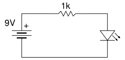
Beginner's Tutorial 1: Building a Circuit on Breadboard - how to build a simple and easy circuit on a breadboard for beginners in electronics. Learn to use an LED and a resistor. This tutorial serves as an introductory guide for...
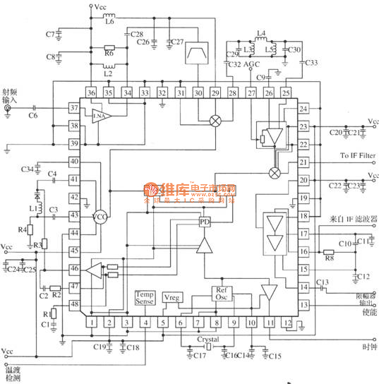
MRFICl505R2 is a 1.575GHz GPS downconverter chip. It integrates a mixer, VCO, PLL, crystal oscillator, A/D converter, loop filter, and other circuits. The MRFICl505R2 IF output frequency is 4.1MHz, with a typical conversion gain of 105dB, an operating voltage...