
Micro-power 32.768kHz clock oscillator circuit

The 32.768 kHz micro-power clock oscillator circuit is designed to provide a stable and low-power clock signal, which is essential for timing applications in electronic devices. The circuit typically employs a crystal oscillator, which utilizes the mechanical resonance of a quartz crystal to produce a precise frequency.
In this configuration, the crystal is connected to an inverter or operational amplifier configured as an oscillator. The output of the oscillator is a square wave clock signal, which can be used to synchronize operations in digital circuits. The low power consumption of this oscillator makes it particularly advantageous for battery-operated devices, ensuring extended operational life.
The circuit should include output terminals that allow for the detection of the clock signal. These terminals enable interfacing with microcontrollers or other digital logic devices that require timing signals. The design may also incorporate decoupling capacitors to filter any noise and ensure stable operation of the oscillator.
Overall, the 32.768 kHz micro-power clock oscillator circuit is a critical component in modern electronic systems, providing essential timing functions while maintaining energy efficiency.Shows a 32.768 kl-b: micro-power clock oscillator circuit, and can be used in mobile phones, laptop computers and home appliances production generates a clock signal supplements. Feet should detect the output clock signal, detecting its feet , feet due oscillator signal.
Related Circuits
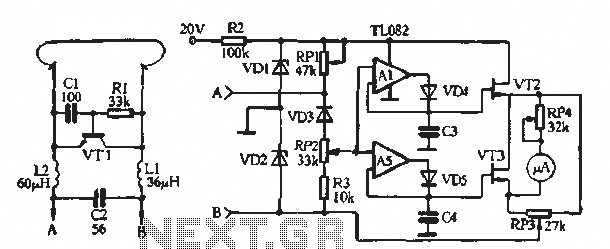
The soil moisture meter circuit is useful for monitoring the moisture levels in plants. It is a simple and effective circuit. The soil moisture meter circuit is designed to measure the volumetric water content in soil, providing valuable data for...

To maintain a constant speed of the motor under varying load conditions, a control application circuit is required. An H-Bridge circuit can be utilized to manage both the speed and direction of the motor. The accompanying diagram illustrates the...
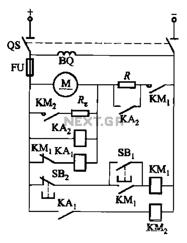
The circuit illustrated in Figure 3-196 features a starting resistance level and an undervoltage relay (KAz) that is controlled by the removal of the startup resistor. It also includes dynamic braking for shutdown purposes. The undervoltage relay (KAL) operates...
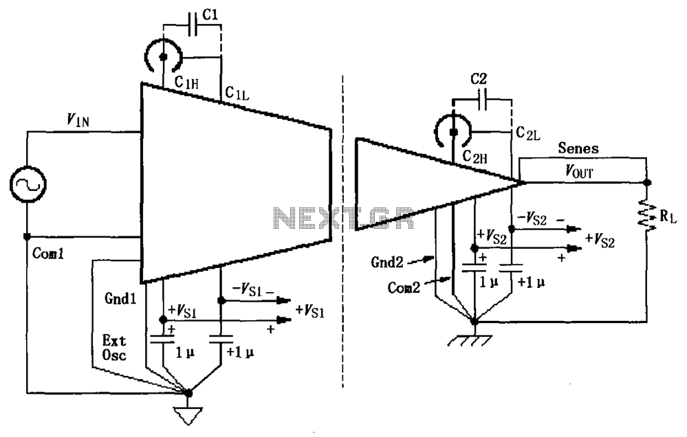
The basic connection circuit for ISO120/121 includes signals and power supply. Each power supply terminal must have a 1 µF tantalum capacitor as a bypass filter, and the printed circuit board layout should allow for the bypass capacitor to...
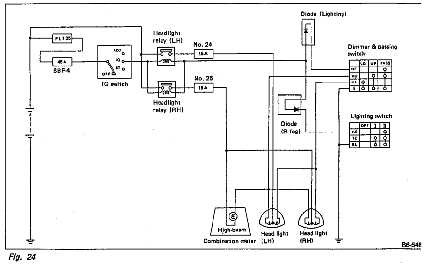
Understanding the headlight wiring in a car involves examining the purpose of two diodes in the circuit diagram. The circuit allows for two independent methods of activating the light relays: through the light switch or by flashing the high...
The double-ended working core square wave inverter transformer area product formula Bm represents the maximum magnetic flux. The primary side of the transformer features switches S1 and S2 in parallel with IRF32055. This parallel configuration is primarily due to...