
FM radio with TDA7000

The FM radio chip described is a compact solution for FM radio applications, integrating multiple functions into a single device, which reduces the need for additional components and simplifies the design. The RF input stage is responsible for receiving the radio frequency signals, which are then processed by the mixer and local oscillator to downconvert the signal to an intermediate frequency (IF). The IF amplifier/limiter enhances the signal strength while maintaining a consistent output level, which is essential for clear audio reproduction.
The phase demodulator extracts the audio signal from the modulated carrier wave, converting it into a format suitable for audio output. The inclusion of a mute detector and mute switch allows for control over audio output, enabling the user to silence the output when needed, which is particularly useful in portable applications to conserve battery life and reduce noise.
The output stage is designed to directly drive a crystal earpiece, making it suitable for personal listening applications. Alternatively, when connected to a TBA820M amplifier, the system can deliver higher audio output levels, making it suitable for broader applications, such as portable radios that require louder sound output.
The accompanying graph provides valuable insights into the performance characteristics of the chip, illustrating how the audio output voltage and total harmonic distortion vary with changes in the input voltage and source impedance. This information is critical for engineers in evaluating the performance of the radio under different operating conditions, helping to optimize the design for specific applications. The ability to enable or disable the muting system also gives designers flexibility in terms of functionality and user experience. Overall, this integrated FM radio solution represents an efficient and effective choice for developing portable radio devices.An FM radio on a single chip requiring only a few simple peripheral components. In particular the ship requires only one simple coil and alignment is very easy. The chip includes an RF input stage, mixer, local oscillator, IF amplifier/limiter, phase demodulator, mute detector and mute switch. The output will directly drive a crystal earpiece or could be used with a TBA820M to form a complete portable radio.
Graph shows AF output voltage(Vo) and total harmonic distortion (THD) as a function of the emf input voltage (EMF) with a source impedance (Rs) of 75ohm : (1) muting system enabled; (2) muting system disabled. Note that the muting system can be disabled b
Related Circuits
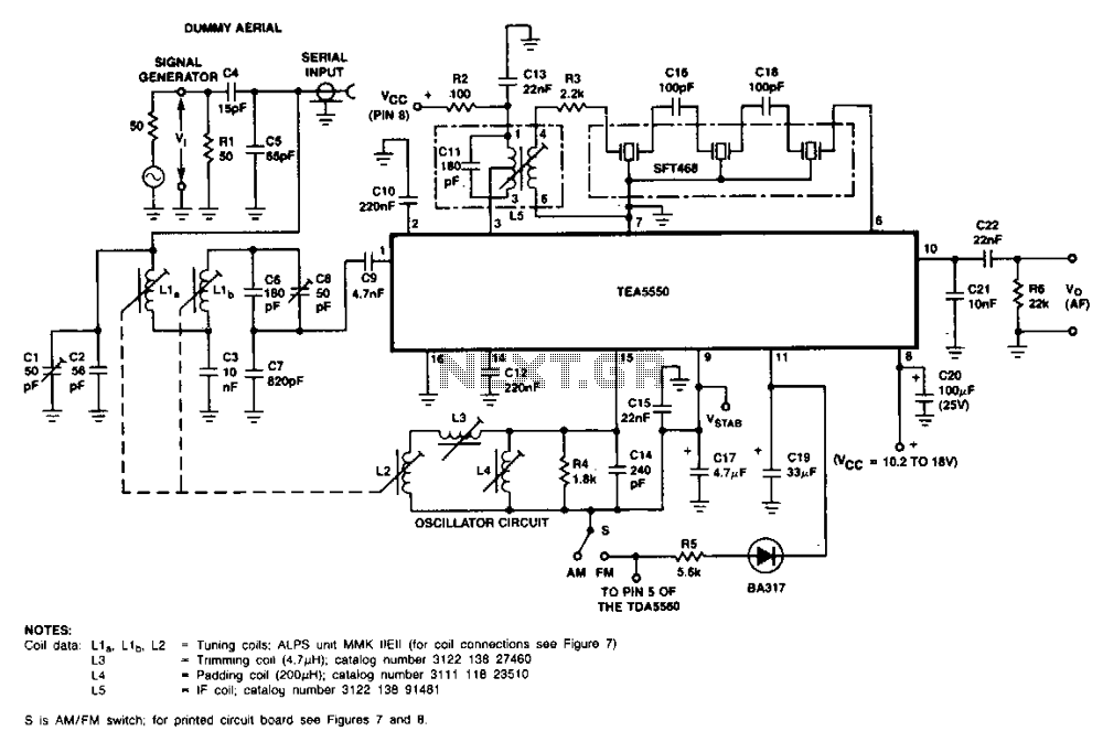
Coil data L1 0, L10, L2 = Tuned CQ<Is: ALPS unit MMK IIEII (for coil connections see Figure 7), L3 -Tuning coil (4.71 µH), L4. Padding capacitor (20 pF), L5. IF Coil. More: This circuit diagram is for a double-tuned, AM-channel, in-car radio receiver using the TEA5550. The described circuit diagram represents a double-tuned AM radio receiver designed for in-car applications, utilizing the TEA5550 integrated circuit. This configuration is particularly effective for enhancing the selectivity and sensitivity of AM signals, making it suitable for automotive environments where interference can be prevalent. The circuit features several critical components, including: 1. **Coil L1, L10, and L2**: These coils are essential for tuning the radio to specific frequencies. The tuning is facilitated by the use of a tuned circuit, which helps in filtering the desired AM signal from the surrounding noise. The designation "Tuned CQ<Is: ALPS unit MMK IIEII" suggests the use of a specific type of coil or inductor that is optimized for this application. The connections for these coils are referenced in Figure 7 of the documentation. 2. **L3 - Tuning Coil (4.71 µH)**: This inductor plays a pivotal role in the tuning process, allowing the circuit to resonate at the desired frequency. The value of 4.71 µH indicates a specific inductance that is crucial for achieving the correct resonance with the associated capacitors. 3. **L4 - Padding Capacitor (20 pF)**: The padding capacitor is used to adjust the overall capacitance in the tuning circuit, which aids in fine-tuning the receiver's frequency response. A value of 20 pF is appropriate for the tuning range of AM frequencies, ensuring that the circuit can effectively filter and amplify the incoming signals. 4. **L5 - IF Coil**: The Intermediate Frequency (IF) coil is responsible for processing the signal after it has been demodulated. This component is vital for further amplification and filtering, allowing the receiver to extract audio signals from the modulated carrier wave effectively. The use of the TEA5550 integrated circuit is noteworthy, as it is designed for low-power applications, making it suitable for automotive use. Its architecture allows for easy integration with the tuning and amplification stages of the radio receiver, providing a compact and efficient solution for in-car audio systems. Overall, this circuit design emphasizes the importance of precise component selection and configuration in achieving optimal performance in AM radio reception, particularly in mobile environments.
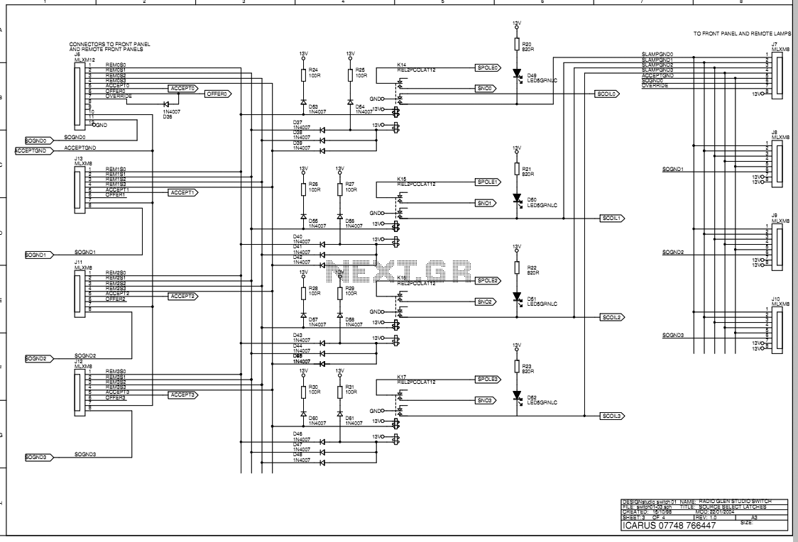
The main box of the Transmit Selector system is designed to be located in the technical rack of a small radio broadcast station. There are four stereo balanced line inputs, either of which can be routed to a stereo...
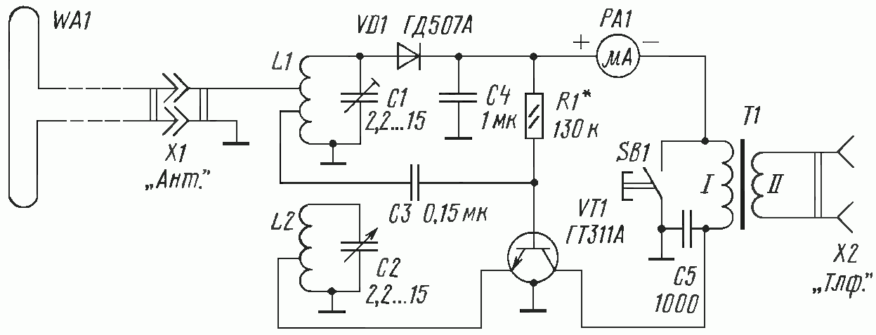
The concept of a "crystal radio" is typically linked with large antennas and radio broadcasting on long and medium bands. This article discusses experimentally tested detector circuits for VHF receivers designed to listen to FM stations. The discovery of...
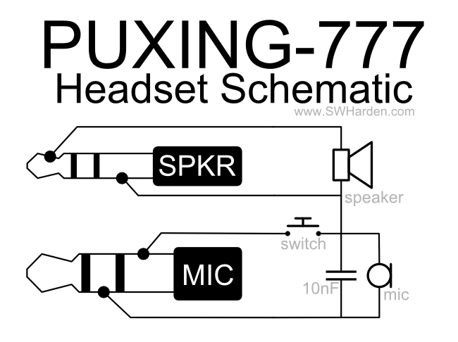
A speaker, microphone, and transmit button circuit designed for the Puxing 777 radio, which is likely compatible with all Puxing radios. The circuit was reverse-engineered from an earphone/microphone headset that originally accompanied the radio to understand its functionality. The...
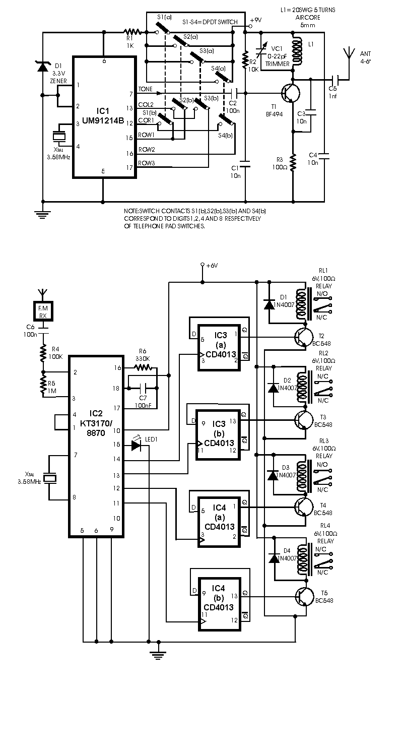
A radio remote control system utilizing DTMF (Dual-Tone Multi-Frequency) technology is presented. This circuit allows for the control of various electrical appliances through radio frequency signals. The described radio remote control system employs DTMF tones, which are generated by a...
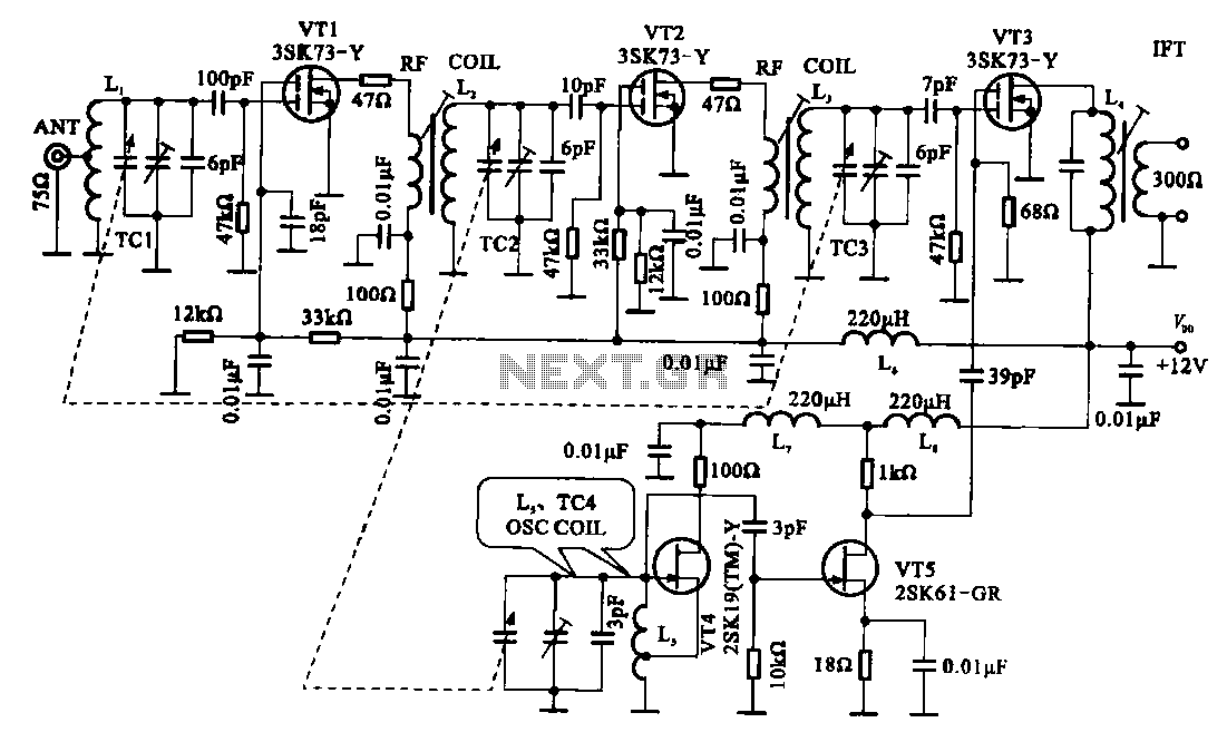
The FM radio circuit is represented by a double-gate MOS field-effect transistor. The high-frequency amplifier is a bipolar MOS field-effect transistor amplifier consisting of transistors VT1 and VT2. VT3 serves as the mixer. The local oscillator is formed by...