
FM Receiver

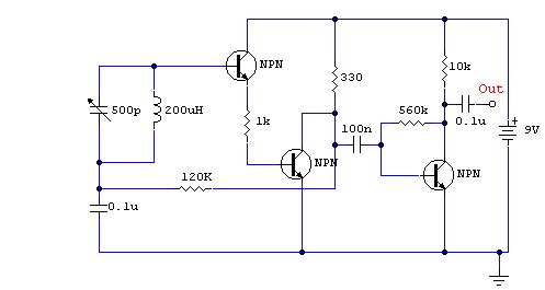
The described circuit is an FM regenerative receiver, which is designed to demodulate frequency modulated signals. The core component of this receiver is a Field Effect Transistor (FET), which is utilized for its high input impedance and efficiency in RF applications. The FET operates in a regenerative mode, where a portion of the output signal is fed back into the input, effectively amplifying the received signal and improving sensitivity.
The regenerative circuit typically includes an LC tank circuit, which is tuned to the desired FM frequency. This tank circuit consists of an inductor and a capacitor, forming a resonant circuit that selects the frequency of interest while rejecting others. The tuning of this circuit can be adjusted using a variable capacitor, allowing the user to scan through different FM stations.
The output from the FET is then connected to an audio amplifier IC. This component is responsible for further amplifying the demodulated audio signal so that it can drive a speaker or headphones. The audio amplifier IC may include features such as volume control, tone adjustment, and power output capabilities suited for driving loads directly.
In terms of power supply, the circuit may operate on a low voltage DC source, which is typical for portable applications. Proper bypass capacitors should be included near the power supply pins of the FET and audio amplifier IC to filter out any noise and ensure stable operation.
Overall, this FM regenerative receiver circuit provides a compact and efficient solution for receiving FM broadcasts, making it suitable for various applications, including hobbyist projects and educational demonstrations in electronics.An FM regenereative receiver using a single FET and one audio amplifier IC. 🔗 External reference
Related Circuits
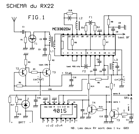
This receiver weighs about 6 g, used in 41 and 72 MHz, met a great success with readers of the magazine. The RX22 is the subject of these lines is improved RX20. Adding a preamp-HF improving sensitivity. Establishment of...
Building a practical and usable direct conversion receiver for the 40 m CW band is not as simple as it might appear. Broadcast station signals from the adjacent 41 m band will easily overload most direct conversion mixer designs...
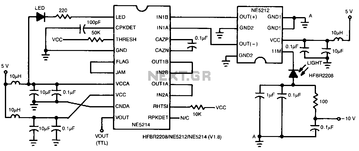
This two-chip receiver, designed for low-cost fiber optic applications at 100-M baud (50 MHz), features a minimal external component count. The receiver consists of pre-amplifier and post-amplifier integrated circuits (ICs) for enhanced stability. The preamplifier IC is characterized by...
The new project utilizes old analog satellite receiver tuners that require modifications to disable the AFC and set the AGC to maximum gain. The output generated is a 480 MHz IF signal. The IF converter may consist of a...
The direct conversion receiver described consists of only a bandpass filter, mixer IC, VFO and audio filter. With only 22 parts, this simple circuit should take a few hours at the weekend to construct. For extra simplicity, eliminate L1...
This is a compact three-transistor regenerative receiver with fixed feedback. It is similar in principle to the ZN414 radio IC, which is no longer available. The design is simple, and the sensitivity and selectivity of the receiver are good....