
AM Receivers

This circuit is designed as a regenerative receiver, which utilizes the principle of positive feedback to achieve amplification of weak radio signals. The configuration employs three transistors, with Q1 and Q2 arranged as a compound pair to maximize gain while maintaining a high input impedance. This is crucial for efficient operation, as it prevents loading the tank circuit, which consists of the ferrite rod and tuning capacitor.
The tuning circuit is specifically tailored for medium wave frequencies, covering a range from 550 kHz to 1600 kHz. The choice of components, particularly the ferrite rod and tuning capacitor salvaged from an old radio, is essential for achieving the desired frequency response. The regenerative feedback provided by the 120 k resistor is a critical parameter; it must be carefully adjusted to balance the circuit's stability and sensitivity. If the feedback is too strong, the circuit will oscillate uncontrollably, while too little feedback will result in poor signal reception.
Transistor Q3 is responsible for demodulating the radio frequency (RF) signal and amplifying the resultant audio signal. The output audio level is contingent on the strength of the incoming signal, typically providing a range of 10-40 mV, which is suitable for driving high-impedance headphones directly or for further amplification if necessary.
When constructing the circuit, it is important to minimize the length of connections to reduce parasitic capacitance and inductance, which can adversely affect performance. A veroboard or tag strip layout is recommended for this purpose. The tuning capacitor's configuration is also critical; the moving plates must be connected to the base of Q1 (the "cold" end), while the fixed plates should connect to the junction of R1 and C1 (the "hot" end). Incorrect connections can lead to instability in the circuit, particularly when external factors, such as hand movement, are introduced.
Overall, this regenerative receiver circuit represents a straightforward yet effective solution for medium wave radio reception, leveraging simple components to achieve good performance in terms of sensitivity and selectivity. Proper adjustment of feedback and careful construction practices will yield a reliable and functional receiver.This is a compact three transistor, regenerative receiver with fixed feedback. It is similar in principle to the ZN414 radio IC which is now no longer available. The design is simple and sensitivity and selectivity of the receiver are good. All general purpose transistors should work in this circuit, I used three BC109C transistors in my prototype . The tuned circuit is designed for medium wave. I used a ferrite rod and tuning capacitor from an old radio which tuned from approximately 550 - 1600kHz. Q1 and Q2 form a compund transistor pair featuring high gain and very high input impedance. This is necessary so as not to unduly load the tank circuit. The 120k resistor provides regenerative feedback, between Q2 output and the tank circuit input and its value affects the overall performance of the whole circuit.
Too much feedback and the circuit will become unstable producing a "howling sound". Insufficient feedback and the receiver becomes "deaf". If the circuit oscillates, then R1`s value may be decreased; try 68k. If there is a lack of sensitivity, then try increasing R1 to around 150k. R1 could also be replaced by a fixed resisor say 33k and a preset resistor of 100k. This will give adjustment of sensitivity and selectivity of the receiver. Transistor Q3 has a dual purpose; it performs demodulation of the RF carrier whilst at the same time, amplifying the audio signal. Audio level varies on the strength of the received station but I had typically 10-40 mV. This will directly drive high impedance headphones or can be fed into a suitable amplifier. All connections should be short, a veroboard or tagstrip layout are suitable. The tuning capacitor has fixed and moving plates. The moving plates should be connected to the "cold" end of the tank circuit, this is the base of Q1, and the fixed plates to the "hot end" of the coil, the juction of R1 and C1.
If connections on the capacitor are reversed, then moving your hand near the capacitor will cause unwanted stability and oscillation. 🔗 External reference
Related Circuits
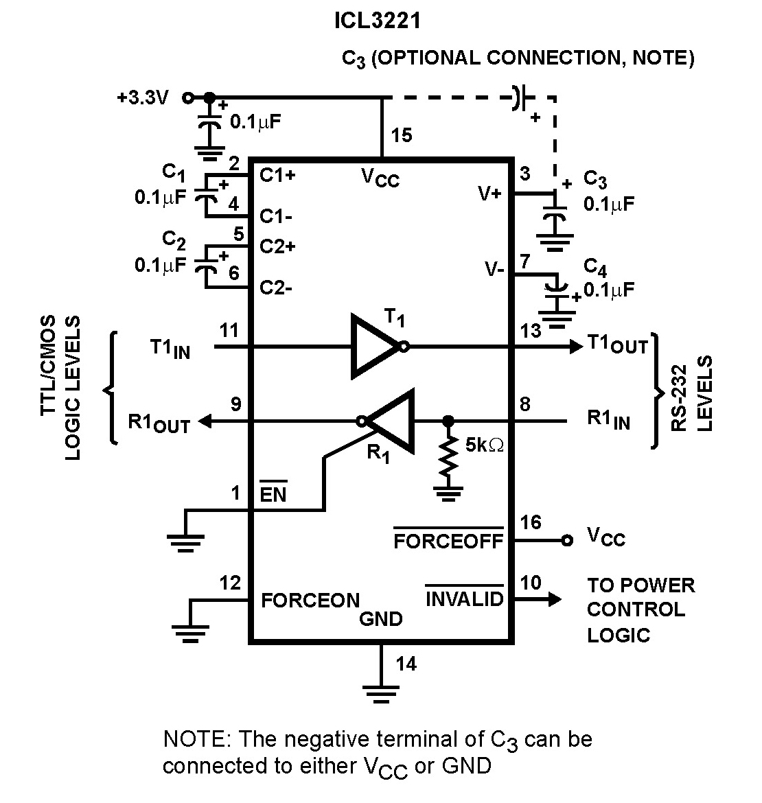
The Intersil ICL32XX devices are powered by 3.0V to 5.5V and function as RS-232 transmitters and receivers, complying with EIA/TIA-232 and V.28/V.24 specifications, even at a supply voltage of 3.0V. These devices are designed for applications such as PDAs,...
This reflex radio project was inspired by Robert Bazian's design. His reflex radio is the "darndest" thing I have seen and his spectacular results inspired me to come up with my own version! These designs are similar to two-transistor...

The individual was not inclined to create and program the timing controller for the PCB laser printer. They recalled having a laser tag gun that had been misaligned during a previous disassembly. The device in question is a Nerf...
An AM receiver depends on the original carrier signal (station frequency) being amplitude modulated, meaning the original amplitude (strength) varies at an audio rate. Figure 1 illustrates an unmodulated carrier signal as it might appear on an oscilloscope, showing...
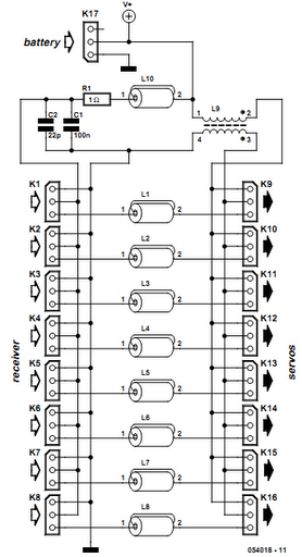
Receiver interference is a common issue among model builders. Preventive measures, such as ferrite beads fitted to servo cables, are frequently employed in larger models and electrically driven models to prevent the cables from acting as antennas and radiating...
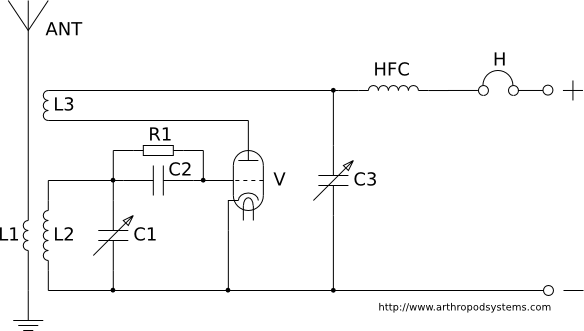
This page discusses various regenerative receiver circuits that were utilized primarily between the 1920s and 1940s. The connections are illustrated using electron tubes (vacuum tubes or valves), although FET transistors can be substituted with minimal adjustments. For radio enthusiasts,...