
FM receivers with PLL

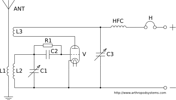
The circuit design incorporates critical components that facilitate the functionality of the FM receiver, including the resonant tank circuits, the phase-locked loop mechanism, and the transistor configurations. The input tank circuit (L1C2) is designed to resonate at the desired FM frequency, ensuring optimal signal reception. The local oscillator (L2C6) is carefully tuned to provide the necessary frequency offset, specifically half of the input frequency, which is essential for the conversion process.
The choice of the GT311E transistor is significant due to its high-frequency capabilities and the ability to operate effectively in both common-base and common-emitter configurations. This dual configuration allows for efficient frequency conversion and amplification, which is crucial for maintaining signal integrity and enhancing audio output. The feedback mechanism involving capacitor C7 is vital for stabilizing the oscillator and improving the gain of the second harmonic, which directly influences the audio output quality.
Furthermore, the network formed by resistors R2 and R3, along with capacitor C3, plays a pivotal role in filtering and shaping the output signal. By adjusting the capacitance of C3, the receiver can be optimized for different types of audio signals, accommodating both stereo and monophonic inputs. The design's sensitivity ensures that even weak signals can be adequately processed without introducing significant noise, which is a common challenge in radio receiver design.
Overall, this FM direct conversion receiver exemplifies an effective integration of components and techniques to achieve reliable performance in VHF signal reception, demonstrating the practical application of electronic principles in radio technology.This article describes some simple FM direct conversion radio receivers with phase-locked loop (PLL). This receivers uses the method of locking the local oscillator frequency with the input signal [1]. All this FM receivers are based on the circuit shown in fig. 1. This is a combined oscillator and mixer, and it works as a synchronous detector. Th e input tank circuit L1C2 tuned to the frequency of the received signal, and the local oscillator circuit L2C6 tuned to a frequency less than input frequency in two times. The conversion occurs at the second harmonic of the local oscillator frequency, so the resulting frequency will be in audio frequency range.
The transistor VT1 provides the frequency control of the local oscillator, the output conductance (it shunts the resonant tank circuit L2C6) of the transistor depends on the collector current, therefore it depends on the output signal of the receiver. VT1 - GT311E (an old USSR Germanium high-frequency transistor with hfe=15. 80 (at DC: Uke=3 V, Ie=15 mA), hfe=2. 5 (at f=100 mHz, Ukb=5 V, Ie=5 mA), Ft = 250) The transistor VT1 is configured as a common-base circuit to work as the local oscillator, and in the same time the transistor VT1 is configured as a common-emitter circuit to work as a frequency converter.
From the wide band resonant tank circuit L1C2 the input signal is applied to the base of the transistor VT1. The resonant circuit L1C2 tuned to the middle of the VHF FM band (70 MHz). The local oscillator tuned to the frequency range of 32. 9. 37 MHz, so the frequency of its second harmonic lies in the frequency range of the VHF broadcasting band (65.
8. 74 MHz - this is the first FM band in Eastern Europe). The efficiency of the detector depends on the level of the second harmonic of the local oscillator in the collector current of the transistor VT1. To increase the amplitude of this component, the capacitance of the capacitor C7 in the positive feedback loop is used in 2.
3 times greater than required for the oscillating at the frequency of the first harmonic. The transistor VT1 is configured as a common-base circuit to work as a synchronous detector. This transistor provides a sound amplification of the audio frequency (this is the low IF), the gain is approximately equal to the ratio of resistors R2/R3. The network R2C3 blocks the RF frequency across the local oscillator, and this network is the load of the synchronous detector.
The time constant of this circuit makes it possible to pass the entire frequency range of the complex stereo signal. The capacitance of the capacitor C3 can be increased to get a standard value of the time constant 50 s in case if the receiver will receive only monophonic signal.
The signal voltage at the output of the receiver is approximately 10. 30 mV (this is enough to listen to the radio with headphones connected to the circuit instead of the resistor R2) and this signal voltage is independent of the level of received radio signal. The sensitivity of this receiver is not worse than a sensitivity of a super-regenerative radio receiver, and this receiver don`t have a "noise" sound when there is no signal of a radio station.
At the moment of tuning of the local oscillator to the half of the frequency of a radio station, the frequency locks and we hear a "click" in headphones, and now the receiver tracks the frequency (in some range) and carrying out synchronous detection of a signal. Because of the PLL and a good isolation between the input resonant circuit and the local oscillator resonant circuit (they has different resonance frequency) the receiver produces very low radiation in the antenna, so the receiver don`t need an RF amplifier.
The shortcoming of the receiver is that the locking range getting wider when a powerful radio signal received, and in this case AM detection may happen, but this is the common problem of all FM direct conversion receivers with PLL. A silicon tr 🔗 External reference
Related Circuits
The notch filter can be integrated into nearly any receiver to attenuate a specific frequency by over 30 dB. This filter is particularly useful for diminishing heterodynes and whistles. A notch filter, also known as a band-stop filter, is designed...
This page discusses various regenerative receiver circuits that were utilized primarily between the 1920s and 1940s. The connections are illustrated using electron tubes (vacuum tubes or valves), although FET transistors can be substituted with minimal adjustments. For radio enthusiasts,...
The AN7158N is an integrated circuit designed for a power amplifier with an output of 7.5W (16V, 4Ω) that features low noise and low distortion. It is suitable for use in television sets with multi-sound capabilities. The design incorporates...
This frequency of this transmitter is PLL controlled which makes it very stable. The frequency is programmed in digitally way and can be changed very easy. Frequency range is about 50 to 150 MHz and the output power 100mW....
The SC9270C/SC9270D is a comprehensive DTMF receiver that integrates both bandsplit filtering and digital decoding functions. The filter section utilizes switched capacitor techniques to achieve high- and low-group filtering along with dial-tone rejection. The decoder employs digital counting techniques...
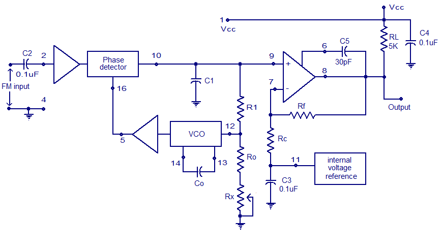
A simple PLL FM demodulator circuit using the IC XR2212 is presented. The XR2212 is a highly stable, monolithic PLL (phase-locked loop) IC specifically designed for communication and control system applications. It operates within a frequency range of 0.01...