
FM Wireless Microphone Transmitter with High Power

The FM Wireless Microphone (v5) circuit design emphasizes simplicity and adaptability, making it an excellent project for hobbyists. The RF amplifier buffer enhances the transmission power, significantly increasing the operational range. The choice of transistors, such as the BC547 and BC557, ensures compatibility with various small-signal applications, enabling easy substitutions based on availability. The inclusion of an AF preamplifier is crucial for improving the microphone sensitivity, allowing for clearer audio capture.
The PCB layout is designed to accommodate the components efficiently, with a focus on minimizing interference and maximizing performance. The spiral inductor L1 not only serves as a critical component for RF transmission but also integrates seamlessly into the PCB design, optimizing space and reducing the need for additional components.
The modification involving the electrolytic capacitor addresses potential stability issues, showcasing the importance of component selection in RF applications. The flexibility in choosing capacitors and resistors allows for fine-tuning the circuit to meet specific requirements, such as varying power supply voltages or adapting to different microphones.
The overall design of the FM Wireless Microphone (v5) reflects a balance between performance and ease of construction, making it suitable for a wide range of applications, from musical instruments to remote control systems. The ability to achieve a significant operational range while maintaining simplicity in design ensures its appeal to both novice and experienced electronics enthusiasts.FM Wireless Microphone has been a very popular project with beginners and experienced constructors alike. It has been used inside guitars and as the basis of a remote control system. I do however, receive many requests for a higher powered circuit and better microphone sensitivity. Now I can introduce the new FM Wireless Microphone (v5), which als o has a better frequency stability, over 1Km range (under ideal conditions) and is good on microphone sensitivity. This has been achieved by adding an RF amplifier buffer (with 10dB gain) and an AF preamplifier to boost the modulation a little.
Construction is quite simple. L1 is 3. 25 turns in spiral form and is an integral part of the PCB foil pattern. The two BC547 transistors can be replaced with (almost) any small-signal NPN transistor, such as the 2N2222. The final stage is a BC557 PNP general purpose device. If you use different devices then you should select the 1M0 resistor for 5-volts DC at the collector of the the first transistor.
Select the 47K resistor for 3 - 4 volts on the collector of the third transistor. Here is the V5 component overlay drawing. Note that there is a modification: There used to be a 1n0 5mm cap for supply decoupling, but after a cange of component supplier (manufacturer ) there developed some form of RF instability when the gain of the PA transistor was a little above normal. Replacing the 1n0 to an electrolytic capacitor of 22uf cured this problem totally. Any "radial" (the leads both come out of the same end) type electrolytic capacitor from 0. 47uf upwards cures the problem. The finished unit draws about 30mA which should vary as you touch the tuned circuit, a good test that the unit is oscillating.
You should remove the 4K7 resistor if you use a dynamic microphone. The PCB is 50mm x 25mm, a little larger than the first version but there are three stages instead of just the one. The first prototype is shown above, beside the battery powering it. The output power is about +10dBm which is about 10dB more than the first FM Wireless Microphone. This would theoretically give it 3. 12 times the range (1. 6Km) but I have only tested it using a handheld receiver with the TX laying on the bench indoors. But I got a comfortable 700 meters (and a few funny looks from our neighbours). Above you can see the addition of a "gimmick" capacitor added across the 12p tuning capacitor to lower the frequency of the transmitter.
Make the capacitor by twisting two lengths of single core insulated hook-up wire, about 2cm long. This will reduce the frequency to the bottom end of the band. Cut short the capacitor to increase the frequency to the desired final frequency. If you cut it a few KHz too high then just twist the gimmick a little tighter. 🔗 External reference
Related Circuits
An emergency light system utilizing white LEDs, which provides several advantages: 1. It is highly bright due to the use of white LEDs. 2. The light activates automatically during a mains power failure and deactivates when mains power is...
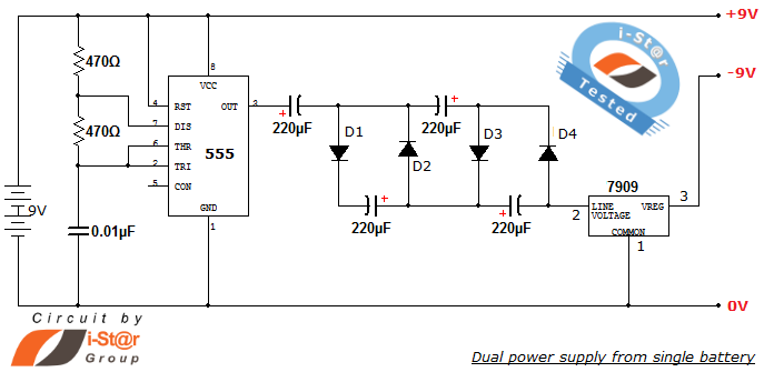
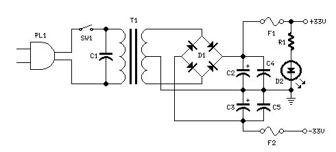
How to create a dual power supply unit using a single battery for laboratory purposes. Dual voltage power supplies are particularly needed for operational amplifier experiments and some instrumentation amplifiers. Additionally, certain low-power audio preamplifiers also require dual voltage...
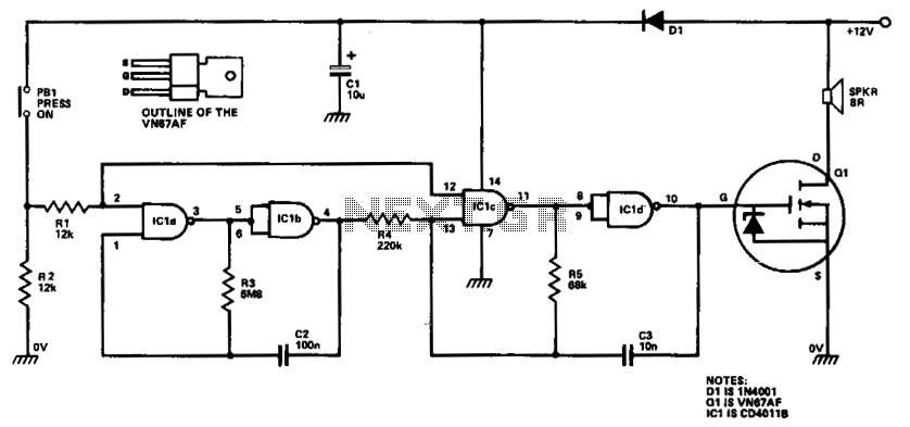
ICla and IClb are configured as a slow astable multivibrator, while IClc and ICld are arranged as a fast astable multivibrator. The output from the slow astable modulates the frequency of the fast astable, and the output from the...
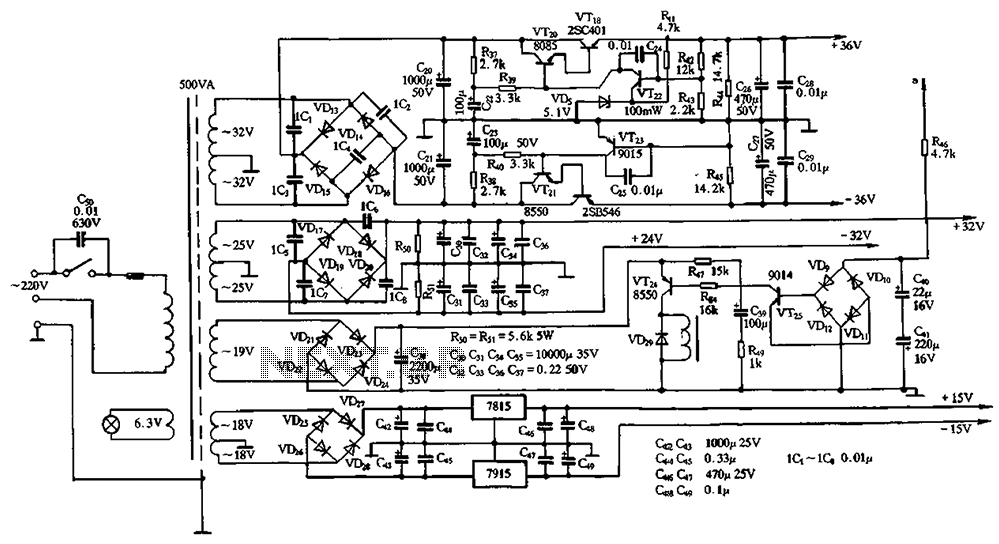
The power supply circuits for servo systems are critical during both the adoption and operational stages. The power supply circuit for servo systems is designed to provide stable and adequate voltage and current levels necessary for the servo motors to...
This transmitter utilizes a 5089 DTMF generator chip along with a keypad to produce DTMF signals, which are then modulated onto an infrared (IR) light beam emitted from an IR LED. The circuit employs a 3.579-MHz TV burst crystal...
Power supply for a 25W power amplifier based on a MOSFET design. This power supply circuit is paired with a high-power audio amplifier rated at 1500 watts. The design of the power supply for the amplifier requires careful consideration....