
force feedback interfacing
The described control system employs a sophisticated closed-loop feedback mechanism to ensure optimal performance across varying airspeeds. The integration of an L272 operational amplifier facilitates precise error correction, enabling the motor to respond dynamically to changes in control stick position. The dual driven potentiometer concept simplifies the complexity of gain adjustment, enhancing the overall efficiency of the system. Careful selection of motor specifications and transistor types ensures that the system can handle the required power levels while maintaining stable operation. The implementation of heat sinks for power transistors underscores the importance of thermal management in high-current applications. The potential for incorporating dynamic flight signals adds an additional layer of interactivity, enhancing user experience through tactile feedback. Overall, this control system represents an advanced approach to managing control forces in response to airspeed, ensuring effective and responsive control in various flight conditions.The first thing I wanted to implement was the control force relation with airspeed. The faster the air flows over the control surface, the more force is needed to make control movements. To make a control system work this way, in the simplest form you need the airspeed and the control surface deflection angle info.
At low airspeed, the force neede d to make control deflections gradually increases, but even at the control limits, the opposing force will still be low. In this operation mode, the control is hardly self-centering. When airspeed increases, the opposing force increases more rapidly with control deflection. In the upper range of airspeed, the centering force becomes very strong. A control system with the above described force effect can be achieved by making a closed loop servo system with adjustable loop gain: An electric motor is mechanically linked to the control stick, while the control stick movement is sensed by a position sensor.
(potmeter) An error amplifier measures the deviation of the control stick position and compares it to a reference. The resulting error signal is amplified, and drives the electric motor that moves the control stick in the direction to reduce the error signal.
The bigger the amplifier gain, the higher the motor drive to move the stick back to reference position. The below diagrams show the basic system and response curves. New Idea: Paul Hanson gave me an idea using a "dual driven potmeter". This is actually much simpler than the gain adjustment method described below. A basic sketch of this idea can be found here. Has been (roughly) tested, and it works. To be worked out further when I have build my 15-channel DAC circuit. The above schematic shows the servo system: I use L272 power OpAmp as error amplier and driver for the NPN/PNP power buffer.
The motor is driven in H-bridge configuration: The right side of the circuit is an inverting amplifier that drives the motor with the opposite signal of the left side. The reference here is a fixed voltage at half the supply voltage. You could add trim control to this reference, in order to shift the servo center position. Also dynamic flight signals could be added to make the stick vibrate or jolt. Depending on the type of motor you use for the force feedback, the current and power handling of the NPN/PNP transistors need to be considered.
DC resistance of the motor will determine the maximum current. In my rudder pedal system, I used a 2. 8 Ohm motor. The current can run up to 6~7Amp. For my flightstick, the current is much lower, about 3A for the elevator and 2A for the aileron. Types like 2N3055/MJ2955 could be used, although too low Hfe could become a driving problem for the L272, which has a max output current of 0. 7A. The diodes can be any standard 3~4A type. At the control center position, the position potmeter wiper is also at half the suppy voltage. As soon as the stick is moved, the position signal differs from the reference voltage. This difference is amplified and drives the DC motor in the opposite direction. The amount of motor drive determines the opposing stick force. By increasing the amplier gain, the motor drive will increase for the same stick deviation. Below some pictures of the servo/buffer. Due to class AB configuration, sufficient heat sinking is needed for the 4 power transistors, as the peak dissipation can go up to 50W when driving the rudder pedals force feedback motor.
Average power is not high, as rudder is mostly in center position during normal flight. Amplifier gain can be changed by reducing the resistor value that is connected to the potmeter wiper. A simple way to achieve this is via a light dependent resistor (LDR). In dark condition, this resistor has a very high resistance. The LDR is light-coupled to an LED. If a current is flowing though the LED, the LDR will reduce in resistance, thus reducing the total resistance connected to the wiper
🔗 External reference
Related Circuits
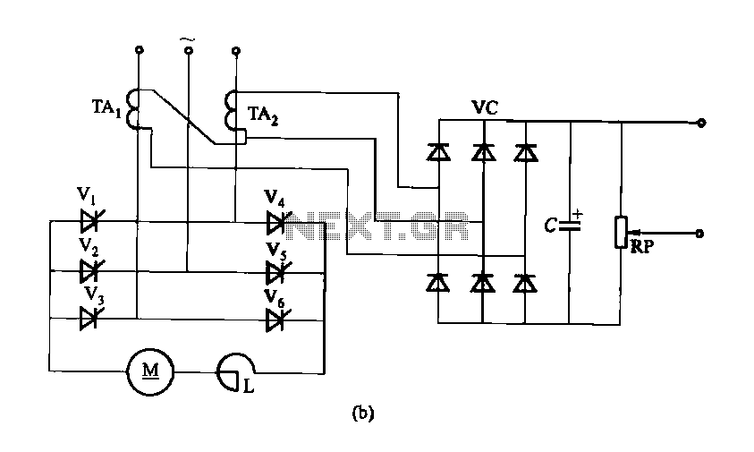
Figure 16-40 illustrates a three-phase rectifier circuit featuring a current cutoff feedback mechanism. In part (a) of the figure, three current transformers are utilized, while part (b) shows the configuration using two current transformers connected in an open delta...
The initial step often taken when learning about any microcontroller or embedded system is to make an LED blink. The circuit presented below illustrates the setup for interfacing an LED. Note: Due to the large dimensions of the circuit...
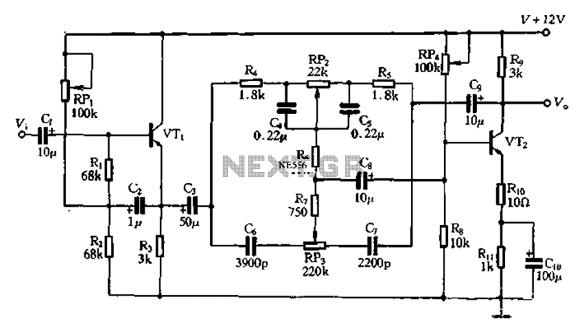
The attenuation circuit is a feedback tone control system that consists of transistors and an RC network. The circuit includes a low tone control potentiometer (RP2) and a treble control potentiometer (RP3). The bass control is influenced by resistor...
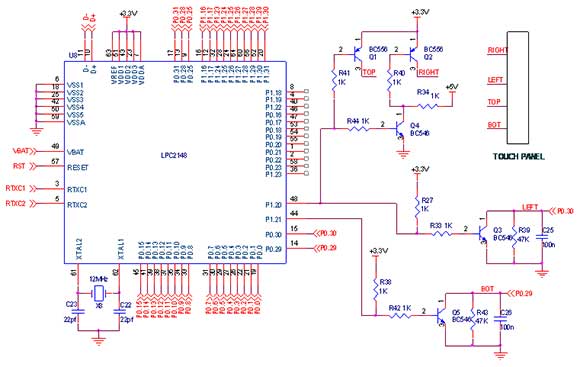
A touch screen is an electronic visual display capable of detecting the presence and location of a touch within its display area. This term typically refers to the interaction with the device's display using a finger or hand, although...
Over time, microcontrollers have become increasingly powerful, cost-effective, and compact. A typical microcontroller from the past may have had 40 pins and lacked internal memory, whereas modern J-series PICs feature 96K of program memory and only 28 pins. This...
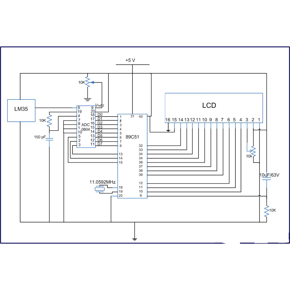
The LM35 series are precision integrated-circuit temperature sensors, whose output voltage is linearly proportional to the Celsius (Centigrade) temperature. The LM35 has an advantage over linear temperature sensors calibrated in Kelvin, as the user is not required to subtract...