
As current feedback circuit of four b

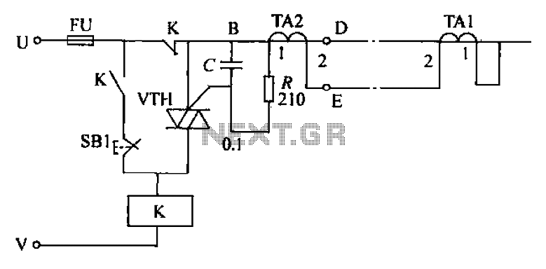
The three-phase rectifier circuit depicted in Figure 16-40 is designed to convert alternating current (AC) from a three-phase supply into direct current (DC). The inclusion of a current cutoff feedback circuit enhances the protection and efficiency of the system by ensuring that the output current remains within safe operational limits.
In part (a), the use of three current transformers allows for precise monitoring of the current flowing through each phase of the rectifier. These transformers provide real-time feedback to the control system, enabling it to adjust the rectification process dynamically. This ensures that any imbalances in the current are detected and corrected promptly, which is critical for maintaining the reliability of the rectifier circuit.
In part (b), the configuration with two current transformers connected in an open delta secondary arrangement offers a more economical solution while still providing effective current monitoring. This setup reduces the number of components required, which can be advantageous in applications where space or budget constraints are a concern. The open delta arrangement allows for the measurement of phase currents while still providing adequate feedback for the control system to function effectively.
Overall, the design of the three-phase rectifier circuit with current cutoff feedback is essential for applications requiring stable and reliable DC power, particularly in industrial environments where three-phase systems are prevalent. The choice between using three individual current transformers versus a pair in an open delta configuration depends on the specific requirements of the application, including factors such as cost, space, and the level of precision needed in current monitoring.Figure 16-40 three-phase rectifier circuit current cutoff feedback circuit. Figure 16-40 (a) use three current transformers; Fig. 16 40 (b) using two connected in open delta se condary current transformer.
Related Circuits
The circuit's current exceeds the load carried by the rated current meter, prompting the user to immediately cut off the power supply to address the overload. Pressing the reset button restores power, making the system simple, convenient, and practical....
This is a 100 Watt inverter circuit designed with a minimal number of components. The circuit utilizes the CD4047 integrated circuit from Texas Instruments to generate 100 Hz pulses, and it employs four 2N3055 transistors to drive the load....
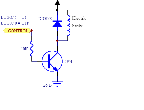
A fingerprint door lock system is being considered for implementation. The primary component is a fingerprint reader that, upon recognizing a valid fingerprint, will instruct an Arduino microcontroller to activate a locking mechanism for a predetermined duration. The locking...
Have you ever attempted to copy a commercially produced video only to end up with a distorted and jumpy image? If so, then you have run afoul of MacroVision. MacroVision is the most popular copy protection scheme used on...
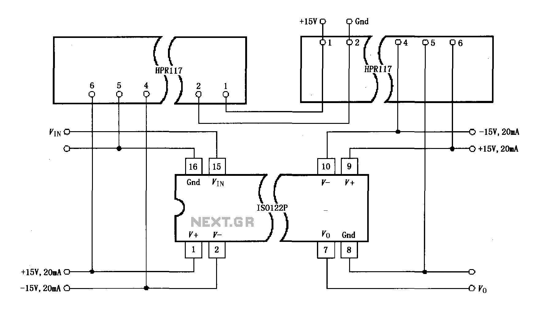
Power isolation is demonstrated for the ISO122P / 124, which features a three-port amplifier. The circuit also utilizes precision analog isolation amplifiers. The ISO122P / 124 isolation amplifier is a cost-effective solution, and the HPR117 DC/DC converter component provides...

The circuit illustrated in the figure features an automatic voltage regulator (T) that utilizes a servo motor to ensure a constant output voltage. The transistors used are VT1 and VT2 (3DK9C, with a range of 65 to 85) and...