
Fox Hunting
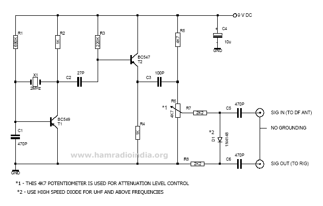
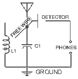
The RDF circuit incorporates a Local Oscillator (LO) that generates a stable frequency, which is critical for mixing with the incoming signal from the hidden transmitter. The diode mixer then combines the LO frequency with the FOX HOWL frequency to produce an intermediate frequency (IF) that is easier to manage and process. This IF can be adjusted to avoid saturation of the handheld rig's receiver, allowing for more accurate direction finding.
The design emphasizes compactness and efficiency, utilizing a printed circuit board (PCB) for easy assembly and integration into existing antenna systems. The choice of a Pierce oscillator for the LO frequency generation enhances the simplicity of the circuit while maintaining reliability. The use of a 2 MHz crystal provides a stable reference for the oscillator, ensuring consistent performance during operation.
Powering the circuit with a standard 9V battery ensures portability and ease of use in field conditions. The circuit's ability to control signal levels effectively allows users to pinpoint the direction of the FOX transmitter with greater accuracy, especially in close-range scenarios where traditional methods may fail due to signal overload.
Overall, this innovative RDF circuit design represents a significant advancement in the field of amateur radio direction finding, providing users with a practical tool to enhance their skills in T-Hunting and related activities.This is a new gear for Radio Direction Finding (RDF) known as FOX HUNT or called Transmitter Hunting (T-Hunting) or Treassure Hunting. HAM clubs, all over the world, are conducting this SCIENTIFIC GAME occasionally, being which is the only one interesting game in HAM World.
This game helps every HAMs and SWLs to get knowledge about radio direction finding, attenuation techniques and associated things like direct signal and reflected signal detection, orientation etc. When the hidden transmitter (FOX) is at a distance of 30 Kms, we can able to find its direction by using 2-element or 3-element beam antenna (Yagi) as a direction finder to get FOX HOWL (Transmitted Signal - Direction) and we get the exact orientation.
But when we are in close to the FOX (Hidden Transmitter), the `S-Meter` reading on your hand held rig shows full scale reading even if the transmitter is running in low power. Due to this we can`t get the proper orientation of the pin-point to the fox and it is because of the poor shielding (case) of the hand held rig.
Normally every hunter using resistive attenuators (passive attenuators) to reduce the signal level to the hand held. But these passive attenuators can`t work in shorter distance. In close distance the hand held rig will shows full s meter reading without any antenna ! In this clever design we are shifting the exact fox howl - receiving frequency and then controlling the signal level.
So there is no direct penetration of signals into the hand held. In this circuit, there are two major sections, one is the Local Oscillator (LO) and the other is a diode mixer with a level control, if we are selecting a LO frequency of 2 MHz and the fox howl frequency of 145 MHz, then the output from the circuit can be at 147 MHz or in 143 MHz. This circuit is assembled by Pre-college Science Academy Students of NASA at Pasadena city College in California, built twenty attenuators and steel tape yagis during Saturday - morning session for their spring 2001 radio-orienteering project in August.
The origin of the circuit is from PA0ZR. and K0 OV. In their design they used crystal controlled CMOS oscillator modules for LO frequency generation. These module oscillators are little bit costly and different types can`t available in our market. Few months back, VU2ESH-Rajesh had provided me the original article for the reference. I reworked the LO frequency generating section lo be simple, flexible and coast effective. I changed the LO frequency module to pierce oscillator with 2MHz crystal. The entire circuit is made on a small PCB (I have made 2 cm / 8 cm PCBs) which can mounted on boom of a direction finding antenna. For power supply put a 9V battery (6F 22). Attaching this circuit in your RDF antenna you can easily control the signal level even one feet nearer to the fox.
So guys, try this new weapon in the next FOXHUNT. 🔗 External reference
Related Circuits
This 2-meter 144 MHz fox hunt transmitter is utilized in amateur competitions where participants seek to locate a concealed transmitter using primarily homebrewed receivers. The 144 MHz fox hunt transmitter is designed for use in amateur radio competitions, commonly referred...
Interest in creating an antenna rig suitable for use with a handheld transceiver for fox hunting. Suggestions are sought for a cost-effective yet efficient solution. To create an effective antenna rig for fox hunting using a handheld transceiver (HT), several...
A user is seeking assistance with tuning a radio circuit they are building independently for the first time, outside of a classroom setting. The process of tuning a radio circuit involves adjusting various components to ensure proper reception of radio...

This 2-meter 144 MHz fox hunt transmitter is utilized in amateur competitions where a concealed transmitter is to be "hunted" using primarily homemade receivers. The 2-meter 144 MHz fox hunt transmitter is designed for use in amateur radio competitions, commonly...
Building a foxhole radio is rewarding and the basic setup is very simple. It is, however, difficult to adjust, and it may take several attempts to find a proper razor blade for the detector. This is a project that...