
Foxhole Radio tuning

The process of tuning a radio circuit involves adjusting various components to ensure proper reception of radio signals. Key elements in a typical radio circuit include the antenna, tuning capacitor, variable resistor, and the radio frequency (RF) amplifier.
To begin, the antenna captures the radio waves, converting them into electrical signals. The tuning capacitor is crucial for selecting the desired frequency. By adjusting the capacitance, the resonant frequency of the circuit can be altered, allowing the user to lock onto specific radio stations.
In conjunction with the tuning capacitor, a variable resistor may be used to fine-tune the signal strength and quality. This component can help mitigate noise and enhance the clarity of the audio output.
The RF amplifier plays a vital role in boosting the weak signals received by the antenna, making them strong enough for further processing. Properly configuring this amplifier is essential for achieving optimal performance from the radio circuit.
To successfully tune the radio, the user should ensure that all connections are secure and that the components are functioning correctly. It may be beneficial to consult circuit diagrams specific to the radio model being constructed, as they provide valuable insights into component values and configurations.
In summary, tuning a radio circuit requires careful adjustment of the tuning capacitor and variable resistor, along with ensuring the RF amplifier is properly configured to enhance signal reception and audio clarity.Hello everyone, this is my first post here. I am building my first circuit (outside of class) and am having trouble tuning my radio. What I have: So.. 🔗 External reference
Related Circuits
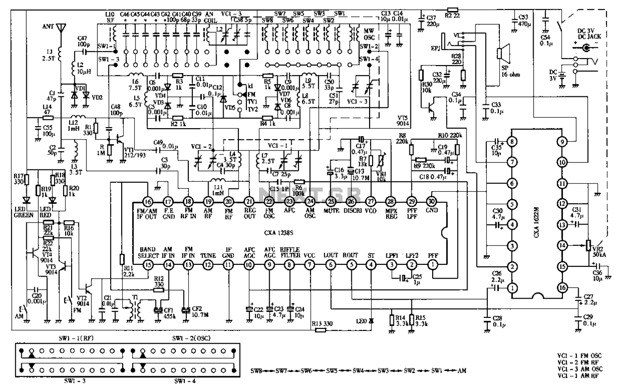
Desheng Rl212A 12-band FM, MW, SW, television sound stereo radio circuit diagram as follows: The Desheng Rl212A is a versatile radio circuit designed to operate across 12 different frequency bands, including FM (Frequency Modulation), MW (Medium Wave), and SW...
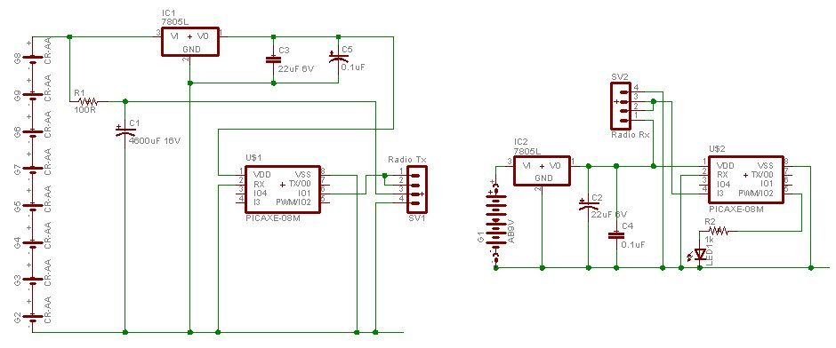
A water tank, dam, or gate can be monitored for vehicle detection without the need for wired connections through the garden. This guide demonstrates how to transmit data reliably over a distance of 500 meters using PICAXE microcontroller chips...
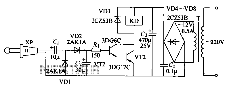
The receiver circuit depicted in the figure requires the insertion of a plug into the radio headphone jack. When the radio receiver detects a signal from the transmitter, an audio signal is output from the jack. This signal is...
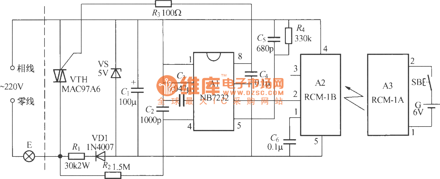
The diagram above illustrates a radio remote control dimmer circuit. This circuit utilizes a micro radio transmit/receive module in conjunction with a light modulation ASIC, resulting in a compact and easily producible design. It operates reliably and features a...
This is a small circuit that provides extra security for radio controlled models. When the signal from the transmitter fails, grab the circuit and set the servo connected to a preset position. The circuit is built around a CMOS...
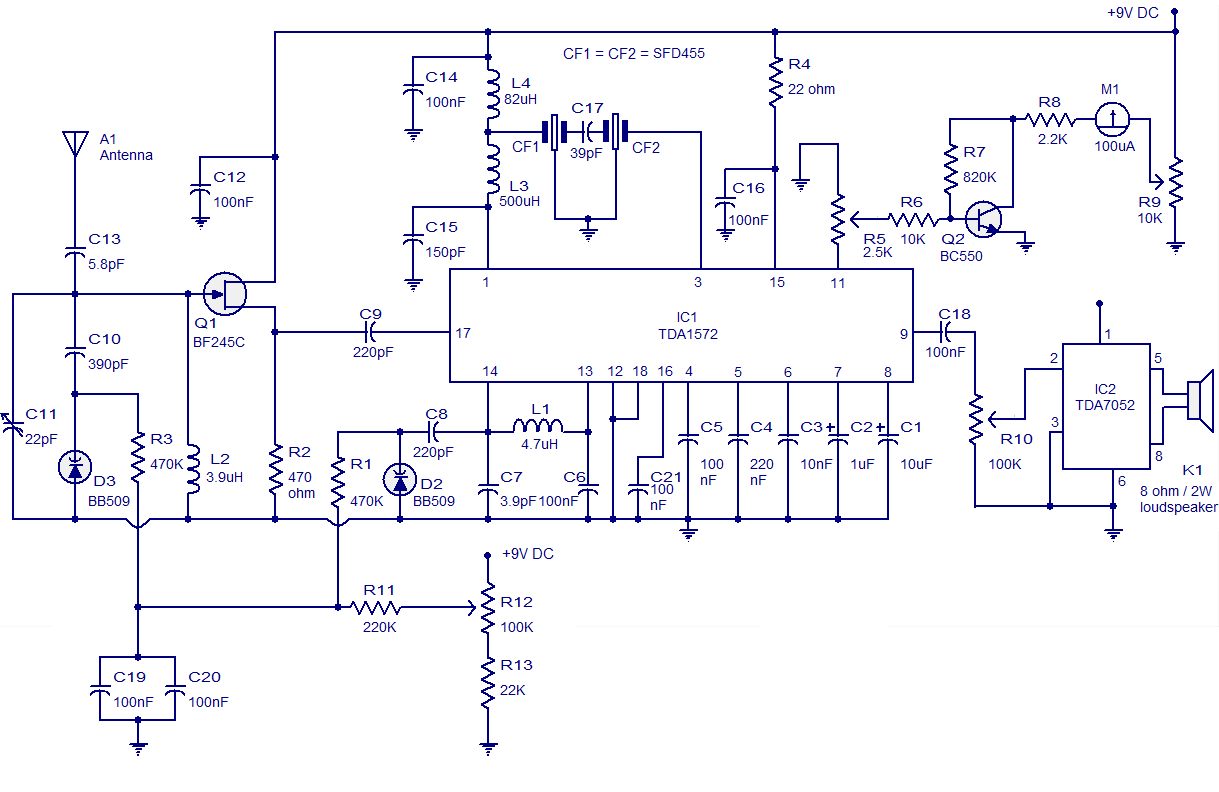
High-quality AM radio circuit based on the TDA1572 IC. The AM radio receiver circuit operates from 9V DC and has a 1W output power. It requires a minimum number of external components. The AM radio circuit utilizing the TDA1572 integrated...