
Free Power Generator Circuit

The antenna design is crucial for optimal performance. It should be constructed using a ferrite core. An 18-foot length of wire should be coiled around the largest ferrite rod available. Multiple ferrite rods can be glued together to achieve the necessary antenna length, with an ideal target being 30 inches or more.
For the diodes, it is recommended to use low-loss germanium diodes with a low breakdown junction voltage, approximately between 0.2 to 0.4 volts. In environments with significant radio frequency interference, each diode may produce around 30 mV. Further details and testing results will be provided in the future.
The described circuit utilizes a simple yet effective method of energy harvesting from ambient radio waves. The antenna, acting as the primary receiver, captures electromagnetic energy from the environment. The choice of a ferrite rod for the antenna enhances the reception due to its magnetic properties, which improve the inductance and efficiency of the antenna design.
The wire length of 18 feet is strategically chosen to resonate at various frequencies typically found in the radio spectrum, allowing the antenna to capture a wider range of signals. The construction of the antenna can be adjusted by adding more ferrite rods, thereby increasing the effective length and improving the overall gain of the system.
Diodes play a critical role in rectifying the alternating current (AC) signals received by the antenna into direct current (DC). The selection of germanium diodes is important due to their low forward voltage drop, which maximizes the efficiency of power conversion. The low breakdown voltage further allows the circuit to operate effectively even under low signal conditions, which is often encountered in urban areas with high levels of radio frequency noise.
The output voltage from the diode rectifiers is dependent on the number of diodes in series, as each diode contributes to the total voltage drop. Therefore, a careful balance must be struck between the number of diodes and the expected output voltage, particularly in environments with varying signal strengths.
Overall, this circuit design presents a viable solution for energy harvesting from ambient radio waves, making it suitable for low-power applications where conventional power sources are impractical. Further experimentation and refinement of the schematic will enhance performance and reliability.You need free power? This schematic transforms the surrounding radio waves to usable current. The levels of power can be stepped up by using more diodes. The critical points in this device are first the type of diodes and second the antenna construction. The more diodes the more power out! And guess what, no ground needed.. Lets begin with the antenna first. It has to be an Ferrite antenna Get a wire 18 feet long and wrap it around the the largest ferrite rod you can find! You can put many ferrite rods glued to make the length of the antenna you need. A 30 inch or more antenna, would be ideal. As for the diodes, try to find the lowest loss Germanium diodes, with the lowest breakdown junction voltage ~ 0.2 - 0.4 Volts.
Keep in mind that in a heavy radio polluted area each diode will put out about 30mV. More details and testings results comming soon..
Related Circuits

A biaxial magnetic field sensor application circuit is illustrated in the figure. This circuit utilizes a biaxial magnetic sensor HMC1002 along with two AMP04 operational amplifiers (A1, A2) to measure the magnetic field in both the X-axis and Y-axis...
This circuit is designed to power a lamp or other appliance for a specified duration of 30 minutes, after which it automatically turns off. It is particularly useful for nighttime reading, as it can turn off a bedside lamp...
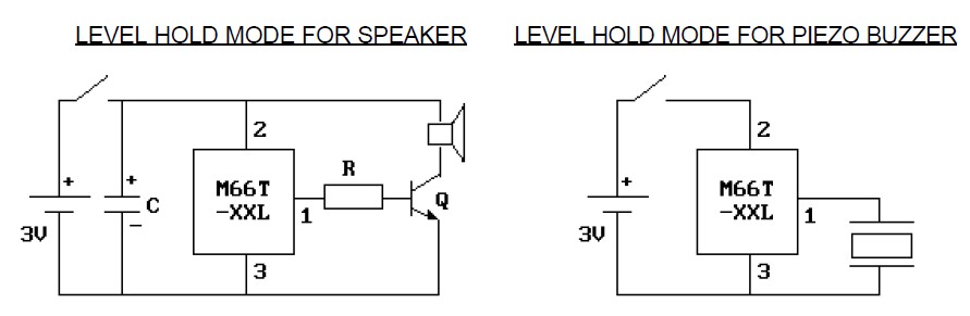
This is a very simple way to play a song using a single 1.5V battery. This circuit can be built for gift accessories. When the gift is opened, a song will be played. It is easy and inexpensive. The...
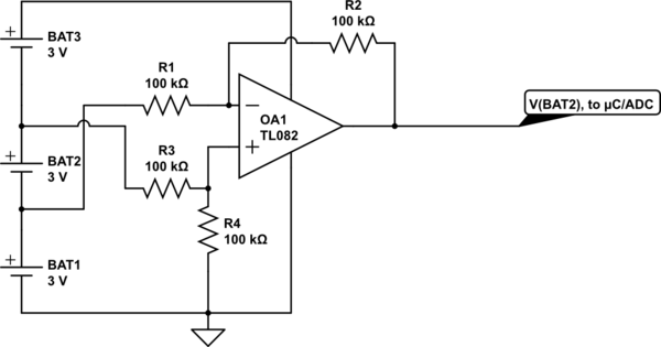
Utilize a high-performance microcontroller (Piccolo TMS320F28035, 12-bit resolution, +/- 4 LSB offset, +/- 60 LSB gain) to measure the voltage across stacked battery cells and control related analog electronics for charge equalization. The microcontroller will also save data in...
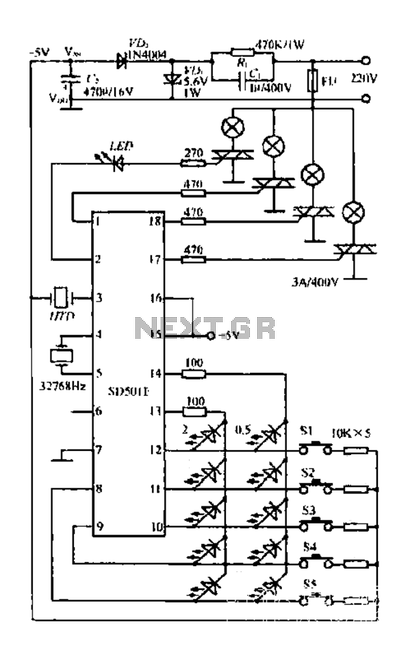
The FIG SD501E is a J tie fan integrated circuit (IC) characterized by progressive timing and three operational modes: strong, medium, and weak. It features three types of output settings and includes an electrical swing mechanism. The device is...
The circuit diagram presented illustrates the MC14093B Fluid Level Sensor Circuit. It is characterized by its compact and simple design, utilizing a single-chip configuration suitable for a wide range of applications. The MC14093B is a CMOS quad two-input NAND gate...