
Application circuit biaxial magnetic field sensor

The described circuit employs the HMC1002 biaxial magnetic sensor to capture magnetic field data in two orthogonal axes, facilitating comprehensive magnetic field analysis. The sensor outputs analog voltage signals that correspond to the magnetic field strength along the X and Y axes. These signals are amplified by two operational amplifiers, AMP04, which are configured to enhance the signal levels suitable for further processing.
The amplified signals are then routed to the TLC2543, a 12-bit analog-to-digital converter (ADC). This ADC converts the analog signals into digital format, allowing for precise measurement and further digital processing. The reference terminal of the TLC2543 ensures that the conversion maintains accuracy and stability, which is crucial for applications requiring high precision.
Powering the circuit is achieved through the MAX662A DC/DC converter, which efficiently steps up the input voltage to the necessary levels. This converter is essential for providing the required voltage to the IRF7105, a power MOSFET used in the circuit. The IRF7105 serves as a pulse current driver, enabling the circuit to handle the necessary output current for driving loads or interfacing with other components.
The input signals for the pulse current driver are sourced from the interface circuit P, ensuring that the system can be integrated seamlessly with other electronic components or systems. The output from the driver is directed to the S/R+ terminal of the HMC1002, allowing for effective communication and control of the sensor's operation.
The inclusion of tantalum capacitors, as specified in Figure C3, is important for maintaining stability and filtering within the circuit. These capacitors are known for their reliability and performance in various electronic applications, making them suitable for this high-performance magnetic sensing circuit. Overall, this circuit design exemplifies a robust approach to measuring and processing magnetic fields in two dimensions, suitable for various applications in fields such as robotics, navigation, and industrial automation. Biaxial magnetic field sensor application circuit as shown in FIG. Using a biaxial magnetic sensor HMC1002, two AMP04 (A1, A2), the magnetic field can simultaneously measure th e X-axis direction and the Y-axis direction. HMC1002 two voltage signals outputted respectively after A1 and A2 amplification, then the analog input and the reference terminal 12 bit A/D converter TLC2543, and then connected via the interface circuit P. MAX662A is a highly efficient DC/DC converter can be raised to + 5V power supply + 10V, as the drive power IRF7105.
Pulse current driver input signal from the P, the output is sent to the HMC1002 S/R + terminal (pin 16). Figure C3 tantalum capacitors should be used.
Related Circuits
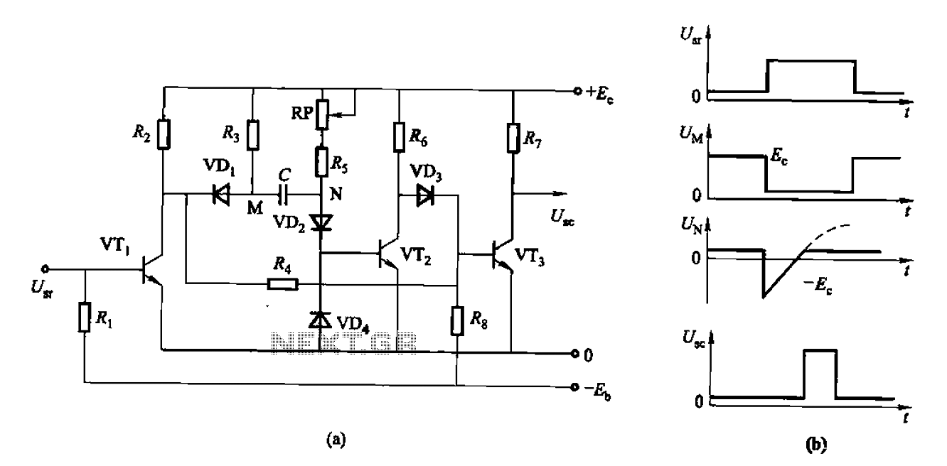
The circuit described is a discharge delay circuit that offers a longer delay compared to a standard rechargeable delay circuit, while also maintaining relatively high accuracy. The schematic diagram illustrates the input and output waveforms. Typically, when there is...

FAN7710 Ballast Control circuit design for Compact Fluorescent Lamps electronic project. The FAN7710 is a specialized integrated circuit designed for the control of ballast systems in compact fluorescent lamps (CFLs). This circuit typically operates in a high-frequency range, facilitating efficient...
Setting circles on an astronomical telescope are used as an aid to point the telescope at a specific object in the sky based on the object's celestial coordinates. However, setting circles can be challenging to use effectively and are...
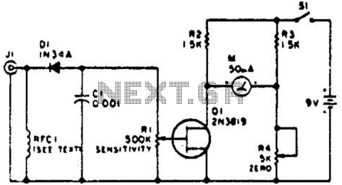
This circuit employs a FET as a DC amplifier within a bridge configuration. Resistor R4 is adjusted for meter nulling with switch J1 short-circuited. Any surplus 50-mA meter can be utilized in this circuit. RFC1 represents a suitable RF...
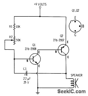
R2 controls the charging speed of capacitor C1. At a specific charge level, C1 triggers transistors Q1 and Q2, which release a 9-volt pulse. This pulse generates a clicking sound. The discharge process of the capacitor involves it charging...

A schematic diagram for a broadband QRP SWR metering circuit intended for use in a QRP antenna tuner. The circuit allows the user to press a momentary DPDT switch to observe an LED indicator while adjusting the capacitors of...