
Frequency Converter Circuit

The 35.3 to 10.7 MHz converter circuit is an essential component in the process of demodulating television audio signals transmitted in FM format. This circuit functions by taking a high-frequency signal, specifically at 35.3 MHz, which is typically output from a VHF/UHF tuner, and converting it to a lower frequency of 10.7 MHz. The 10.7 MHz frequency is a standard intermediate frequency (IF) used in FM tuners, facilitating the decoding of audio signals for playback.
The primary components of this converter circuit may include a mixer, local oscillator, and bandpass filter. The mixer plays a crucial role in combining the incoming 35.3 MHz signal with a local oscillator signal, which is set to a specific frequency that allows for the desired downconversion to 10.7 MHz. The output of the mixer is then processed through a bandpass filter to isolate the 10.7 MHz signal while rejecting unwanted frequencies.
To ensure optimal performance, careful attention must be given to the design parameters of the local oscillator, including its stability and frequency accuracy. Additionally, the choice of components such as RF amplifiers and filters will significantly impact the overall signal quality and noise performance of the converter circuit.
This circuit is widely utilized in various applications, including television receivers and other audio decoding systems, where efficient signal processing is necessary for high-quality audio output. Proper implementation of this converter circuit will enhance the listening experience by providing clear and reliable audio from television broadcasts.This is a 35.3 to 10.7 MHz converter circuit. It converts the 35.3 MHz signal coming from a VHF/UHF tuner down to an FM tuner to decode the TV audio in FM.. 🔗 External reference
Related Circuits
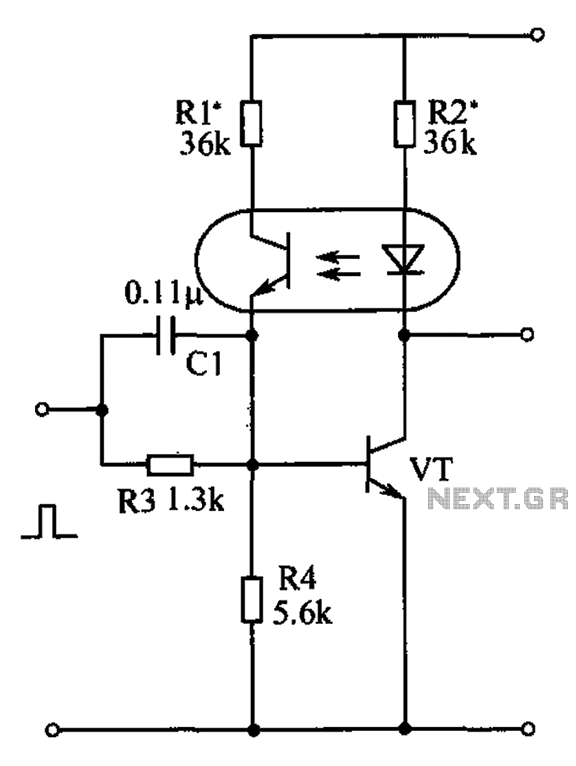
The bistable circuit and optocoupler transistor operate as illustrated in the accompanying figure. Initially, when the supply voltage is applied, the transistor VT is in the off state, resulting in a high output potential. Upon receiving a forward pulse...
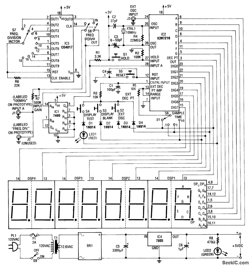
Built around an Intersil 7216 frequency-counter IC, this counter features a basic frequency range of 10 MHz, complemented by a 100-MHz prescaler and an additional frequency divider (IC3). This divider further extends the counting range by dividing the frequency...
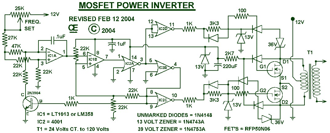
1000W Power Inverter circuit diagram: This is a power inverter circuit based on the MOSFET RFP50N06. The inverter is capable of handling loads up to 1000W, depending on the specifications of the transformer used. The RFP50N06 MOSFETs are rated...
The circuit features an adjustable prestage utilizing the AF279 transistor, while the natural oscillation mixer stage employs the AF280 transistor. The power circuit is mounted on a board with copper coating. The main coil specifications are as follows: L1,...
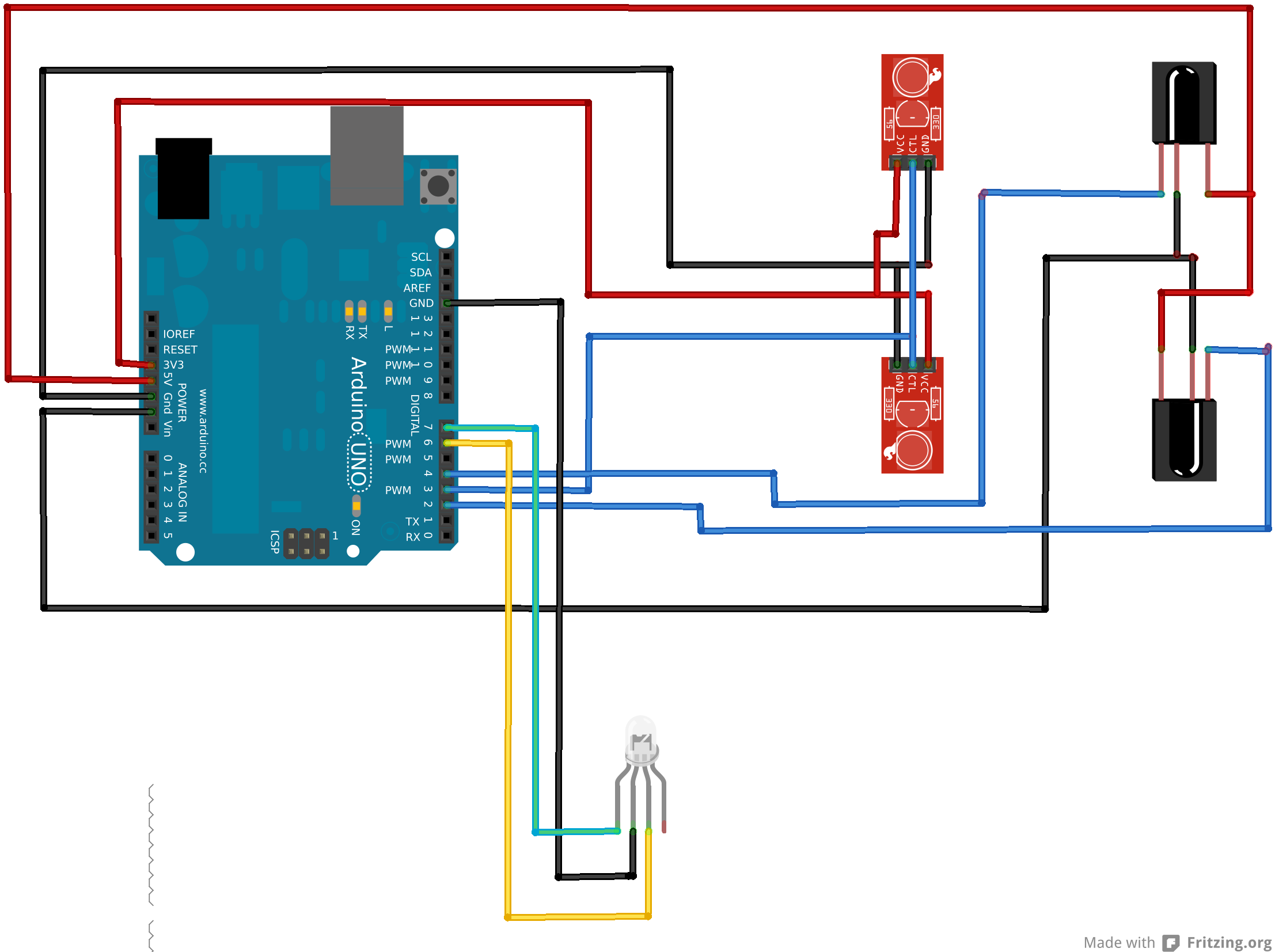
An Arduino Uno is connected to two infrared (IR) transmitters and their respective receivers. When one of the receivers detects a beam break, a strand of LEDs displays a pattern. While this setup functions correctly in principle, an issue...
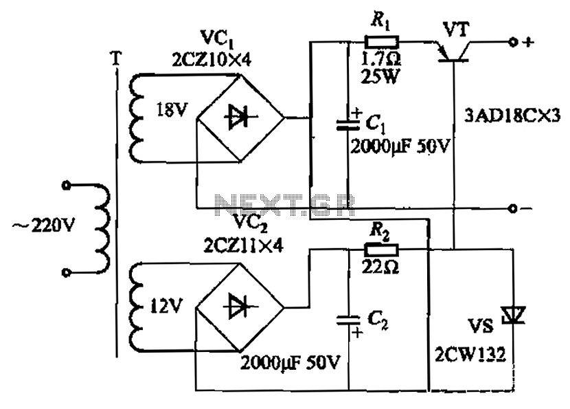
Characterized by a steady flow of power when the power supply voltage fluctuates or the load changes, this circuit maintains a constant load current. The output current of the circuit is illustrated in Figure 4A. When the load varies...