
Transistors UHF tuner circuit

The circuit design incorporates a key adjustable prestage that enhances signal processing capabilities. The AF279 transistor is selected for its high-frequency performance, enabling efficient amplification of weak signals before they are mixed in the subsequent stage. The natural oscillation mixer stage, utilizing the AF280 transistor, facilitates the combination of the amplified signal with a local oscillator signal, producing an intermediate frequency that can be further processed.
The power circuit's copper-coated board not only provides a robust substrate for the components but also aids in effective thermal management and signal integrity. The choice of eight turns for coils L1, L3, L8, and L9, using 0.35mm copper enameled wire, is critical for achieving the desired inductance values while maintaining physical compactness. The 3mm diameter of the coils allows for adequate spacing and minimizes parasitic capacitance, which can adversely affect circuit performance.
Coil L2, with three turns, is likely designed for a specific function, possibly serving as a coupling or feedback element. Coils L10 and L11, each with fifteen turns, may be configured to enhance selectivity or improve impedance matching within the circuit, contributing to overall efficiency and performance. This configuration of coils is essential for optimizing the circuit's response across its operational frequency range, ensuring reliable and effective signal processing.In the circuit, the adjustable prestage is composed of transistor AF279, and the natural oscillation mixer stage consists of transistor AF280. The power circuit is installed on the board with copper coating. The main coil data:L1, L3, L8, L9: eight turns, the coil uses 0.35mm copper enameled wire with diameter in 3mm;L2 : 3 turns, L10 : 15 turns, L11: 15 tur..
🔗 External reference
Related Circuits
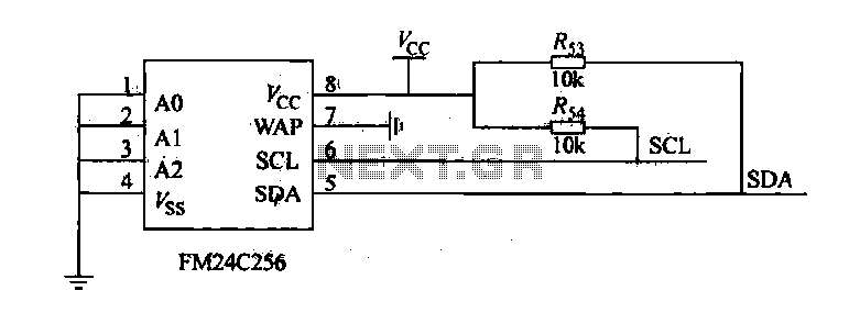
The FM24C256 is utilized as a slave interface circuit in an I2C bus configuration, with the address format specified in Table 27-3. The address pins A2, A1, and A0 are set to low; however, for extended storage capacity, adjustments...
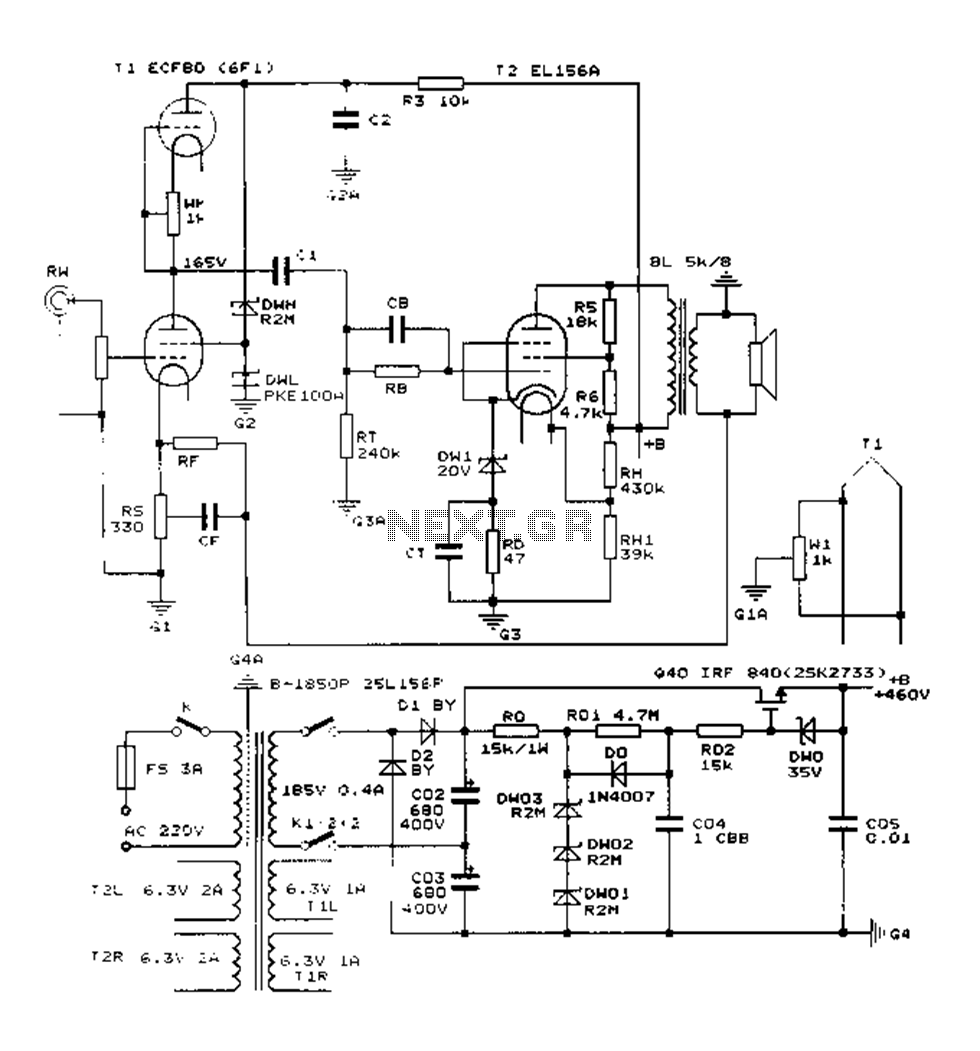
The Danji mellow sound is characterized by its transparent and natural quality, offering a sweet and sincere listening experience that is tireless over long durations and rich in humane color. Tube amplifiers have become an audiophile's companion and are...
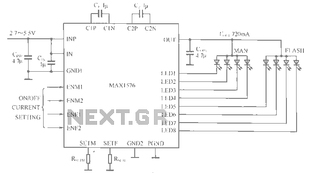
The MAX1516 charge pump drives up to 8 white LEDs with constant current regulation to achieve uniform light intensity, capable of delivering up to 30mA per LED for backlighting. The flash group LEDs (LED5 to LED8) are individually controlled,...
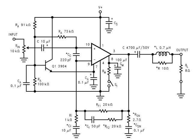
The LM2876 audio power amplifier circuit can be designed as a simple, high-efficiency power audio amplifier capable of delivering 40W of continuous average power to an 8-ohm load with a total harmonic distortion plus noise (THD+N) of 0.1% from...
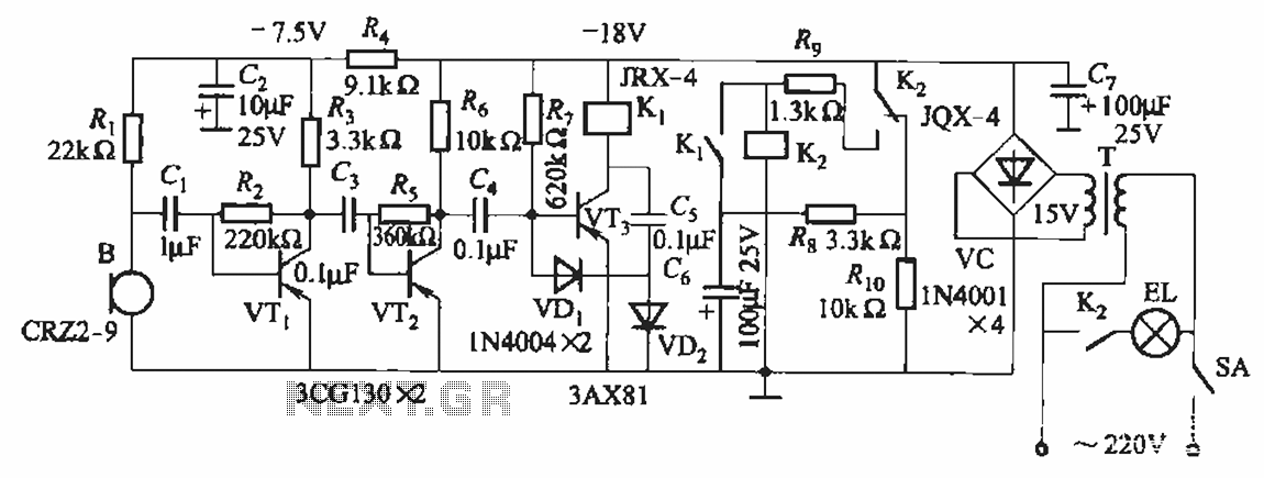
The circuit utilizes relay control. The voice switch operates as follows: upon the first clap, the load (lights) is activated; upon the second clap, the load (lights) is deactivated. This system can be employed to control lighting in residential...
The RF power amplifier circuit described here utilizes the transistors 2SC1970 and 2N4427. This FM RF amplifier operates within the frequency range of 88-108 MHz, delivering an output power of approximately 1.3W from an input driver of 30-50mW. The...