
FREQUENCY COUNTER PREAMP

The described circuit employs a preamplifier designed to enhance the sensitivity of signal detection in various applications, particularly in radio frequency environments. The use of shielded cable minimizes electromagnetic interference, ensuring that the signals remain intact during transmission to the counter. The DPDT (Double Pole Double Throw) switch allows for flexible operation, enabling users to bypass the preamplifier when amplification is not required, thus conserving power and reducing noise.
In scenarios where the preamplifier is utilized as a receiver, its ability to increase signal strength by 6 S-units at 30 MHz demonstrates its effectiveness in improving the clarity and reliability of received signals. This characteristic is particularly advantageous in environments with weak signal conditions, allowing for better performance in communication systems.
The inclusion of a line tap in the circuit design facilitates direct frequency measurement from the transmitter output. With a simple configuration comprising two diodes, a resistor, and a capacitor, the line tap is capable of sampling low-amplitude signals without significantly affecting the main transmission line. This feature is crucial for monitoring and analyzing the frequency output of transmitters, making it suitable for applications in amateur radio and other RF communication systems.
The circuit is designed to accommodate a wide range of transmitter output power, from 1 W to 250 W, ensuring versatility in various operational contexts. This adaptability is essential for users who may need to interface with different equipment while maintaining accurate frequency measurements. Overall, this preamplifier and line tap circuit represents a robust solution for enhancing signal detection and measurement in electronic communication applications.By using the preamplifier with a short length of shielded cable and clip leads, signals that generally could not generate a readout, generate precise and stable readouts on the counter. The DPDT switch is used to bypass the circuit when amplification is not needed. The preamplifier can also be used for other purposes. For example, the unit was als o tested as a receiver preamplifier and increased received signal strength about 6 S-units at 30 MHz. A line tap can be used to measure the frequency directly at the output of a transmitter. The entire circuit for that consists of two diodes, one resistor, and one capacitor. The line tap simply picks a low-amplitude signal for measurement by the frequency counter. The tap can be connected to transmitters with an output power of between 1 and 250 W. 🔗 External reference
Related Circuits
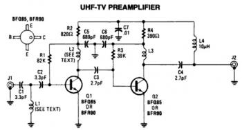
This is a low-cost, antenna-mounted UHF TV pre-amplifier circuit that can provide more than 25 dB of gain. The first stage of the pre-amplifier is biased for optimum gain. L1 and L2 are strip line equivalents with a length...
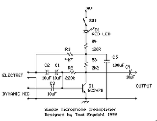
The circuit is a simple one-transistor amplifier with an amplification factor of approximately 30-40 dB, which varies depending on the transistor, temperature, and voltage. The dynamic microphone input is a straightforward one-transistor amplifier circuit with no special features. LED...
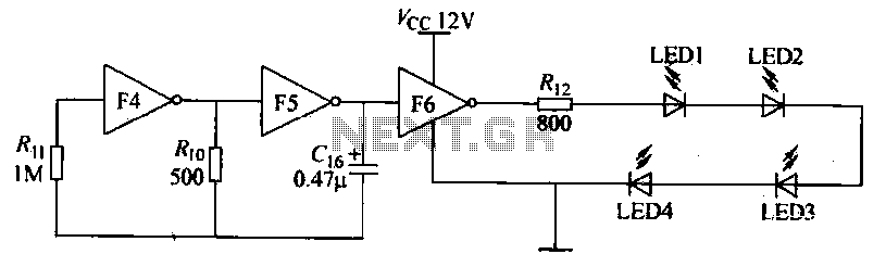
Gates F4, F5, and F6 together form a low-frequency oscillator that drives high-brightness light-emitting diode (LED) flashes. The light-emitting diodes may be arranged around the booth seat for decorative purposes. The automatic referral machine is used prior to operation...

This circuit is designed for an RF (radio frequency) transmitter experiment, where a watt meter is instrumental in optimizing the transmitter circuit. A simple RF watt meter circuit is illustrated in the schematic diagram below. The circuit is not...
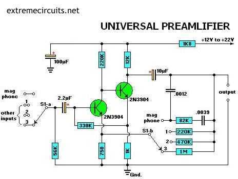
Most audio amplifier systems must have preamplifiers with many different characteristics. These include high-gain linear response for magnetic microphones, low-gain linear response for tuners, and high-gain RIAA equalization for magnetic phone cartridges. To meet this broad requirement, most amplifier...
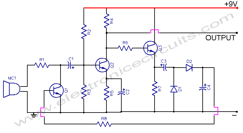
This microphone preamplifier incorporates automatic gain control, which keeps the output level fairly constant over a wide range of input. The microphone preamplifier is designed to enhance the audio signal from a microphone while maintaining a consistent output level. The...