
General use Preamplifier with 2N3904

The universal preamplifier circuit is designed to accommodate various audio sources by adjusting its gain characteristics through a flexible feedback network. The primary function of this circuit is to amplify low-level audio signals from sources such as microphones and turntables, ensuring optimal signal integrity and compatibility with downstream audio processing equipment.
In the circuit configuration, a high-gain linear amplifier is employed, typically utilizing an operational amplifier (op-amp) as the core component. The op-amp is configured in a non-inverting mode, allowing for high input impedance, which is essential for interfacing with sensitive audio sources. The gain of the amplifier is determined by the feedback resistors connected to the op-amp's feedback loop.
The selector switch S1-a allows for the selection of different audio input sources. When the switch is set to the Mag phono position, it engages a specific pathway tailored for magnetic phono cartridges, which require RIAA equalization to compensate for the frequency response of vinyl records. This equalization is achieved through a combination of capacitors and resistors that form a filter network, specifically designed to boost low-frequency signals and attenuate high-frequency signals, aligning the output with standard RIAA playback curves.
The feedback resistors S1-b are critical in adjusting the gain of the preamplifier. By providing a choice of resistor values—220K, 470K, and 1M ohms—the circuit allows the user to customize the gain according to personal preferences and the specific requirements of the audio source. The relationship between the feedback resistor value and the circuit gain is direct; higher resistance values result in increased gain, while lower values provide reduced amplification.
The range of feedback resistor values from 10 kilo ohms to 10 megohms further enhances the versatility of the preamplifier, accommodating a wide array of audio devices and listener preferences. This adaptability is crucial in professional audio applications, where precise control over signal amplification can significantly impact sound quality and overall system performance.
In summary, the universal preamplifier circuit serves as a vital component in audio amplifier systems, providing the necessary gain adjustments and equalization to ensure high-fidelity sound reproduction across various audio sources.Most audio amplifier systems must have preamplifiers with many different characteristics. These include high-gain linear response for magnetic microphones, low-gain linear response for tuners, and high-gain RIAA equalization for magnetic phone cartridges. To meet this broad requirement, most amplifier designers include a single universal preamplifier circuit.
Basically a high-gain linear amplifier, its characteristics can be altered by switching alternative resistor filter networks into its feedback system. For example, when the selector switch is set to the Mag phono position, alternative input sources can be selected by S1-a, and appropriate linear-response gain control feedback resistors 220K, 470K, and 1M are now selected by S1-b. Those feedback resistor values are selected between 10 kilo ohms and 10 megohms to suit individual listener tastes.
Circuit gain will be proportional, to the feedback resistor value. 🔗 External reference
Related Circuits
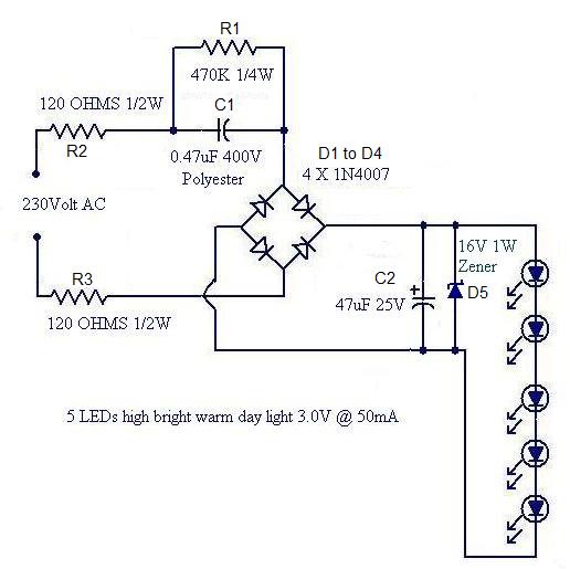
Convert a used CFL into a power-saving LED lamp circuit that consumes only 50mA. This gadget can be used in applications like a night light, table lamp, etc. The project involves redesigning a compact fluorescent lamp (CFL) to function as...
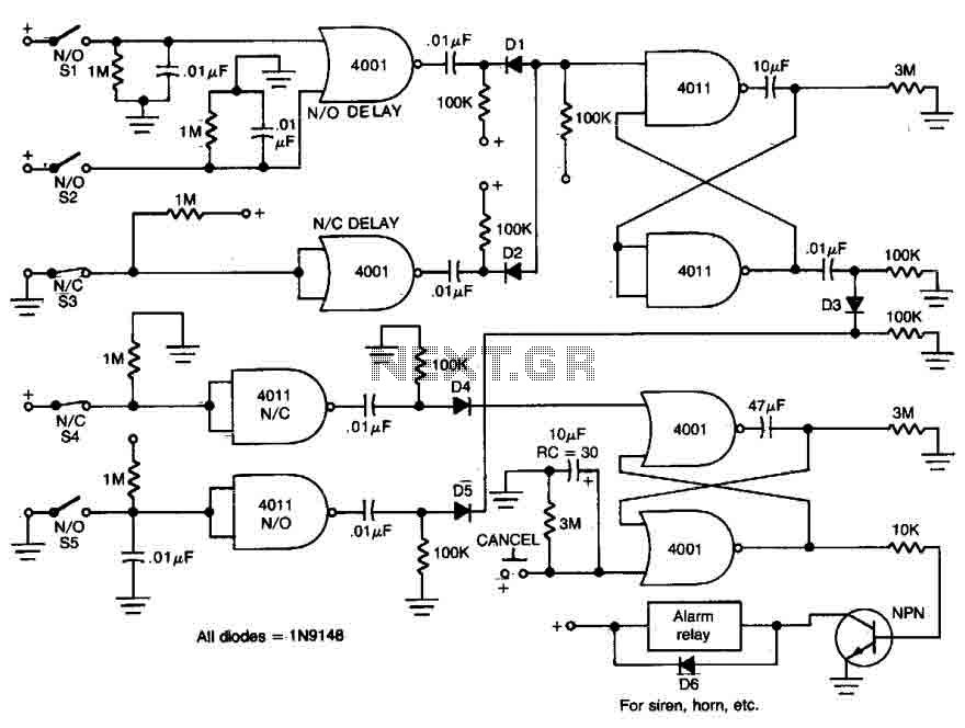
This circuit features open and closed loop contacts (switches 1, 2, 3) that activate the alarm, which remains on for a duration of 5 to 10 minutes. The triggering delay for entrance and exit is set to 27 seconds....
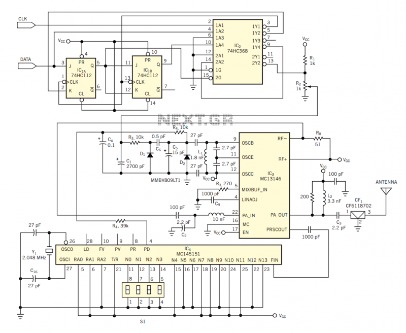
The circuit in Figure 2 shows a 16-channel, AMI-encoded RF transmitter for data rates as high as 28.8 kbps. The circuit operates in the unlicensed (FCC Part 15) 902- to 928-MHz industrial, scientific, and medical (ISM) band and is...
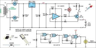
This circuit charges two NiCad cells with a constant current and features dual charging rates, voltage cutoff, and an audible alarm. The circuit is powered. This circuit is designed to efficiently charge two nickel-cadmium (NiCad) cells, utilizing a constant current...

The TPS61200 specifications indicate that GND serves as the control/logic ground, while PGND is designated as the power ground. However, this distinction is not accurately represented in the symbols used in the diagram. There is also confusion regarding the...
Why use one resistor and one transistor for each LED instead of connecting the LEDs in series and controlling them with a single transistor? This approach is controlled by an Arduino pin through a single resistor. While there is...