
Fridge Door Alarm Schematic 2nd Version

The circuit design focuses on enhancing the reliability of the Fridge Door Alarm by utilizing a more efficient configuration that operates effectively at lower voltage levels. The core components include two integrated circuits (IC1 and IC2), a photoresistor (R2), a capacitor (C1), a resistor (R1), a diode (D1), and a Piezo sounder. The integration of the photoresistor serves as a light sensor, which is crucial in determining the status of the refrigerator door.
When the refrigerator door is closed, the light sensor remains inactive, allowing the capacitor to charge and stabilize the circuit. The astable multivibrator configuration of IC1 ensures that once the light is detected, the circuit transitions from a stable state to an oscillating state, which is critical for triggering the alarm system. The output from IC1 is connected to IC2, which also operates as an astable multivibrator, generating the sound output through the Piezo sounder.
The design emphasizes energy efficiency, ensuring that the alarm system can function effectively even with a diminishing battery supply. By utilizing components that are more readily available and simplifying the circuit design, this approach aims to provide a practical solution for hobbyists and users looking for a reliable refrigerator door alarm system that can withstand lower voltage conditions.The main purpose of this design was to obviate a small defect of the very popular Fridge Door Alarm circuit, available on this website since 1999 and built by a lot of hobbyists. Unfortunately, that circuit stops operating when the battery voltage falls below about 2. 6 - 2. 7 Volts. This is due to the 4060 CMos IC used. In some cases, devices made by some manufacturers (but not Motorola`s) fail to operate even at nominal 3V supply voltage. A simple cure to this shortcoming could be the substitution of the original IC specified with a 74HC4060 chip: this should allow circuit operation down to 2V but, unfortunately, this IC is not easy to locate. For this reason, an equivalent circuit using about the same parts counting was developed, in order to allow safe operation even when battery voltage falls down to about 1.
3V. The circuit, enclosed in a small box, should be placed in the fridge near the lamp (if any) or close to the opening. With the door closed, the interior of the fridge is in dark, the photo resistor R2 presents a high resistance (>200K) thus clamping IC1 by holding C1 fully charged across R1 and D1.
When a beam of light enters from the opening, or the fridge lamp lights, the photo resistor lowers its resistance (<2K) stopping C1 charging current. Therefore IC1, wired as an astable multivibrator, starts oscillating at a very low frequency and after a period of about 24 sec.
its output pin (#3) goes high, enabling IC2. This chip is also wired as an astable multivibrator, driving the Piezo sounder intermittently at about 5 times per second. The alarm is activated for about 17 sec. then stopped for the same time period and the cycle repeats until the fridge door closes. 🔗 External reference
Related Circuits
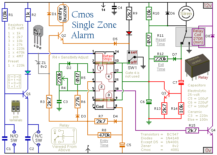
This circuit features automatic Exit/Entry delays, timed Bell Cut-off and System Reset. It has provision for normally open and normally closed switches and will accommodate the usual input devices such as Foil Tape, Pressure Mats, Magnetic Reed Contacts, Passive...

This simple alarm circuit is designed for use in a combined garage and rumpus room. It can be assembled on Veroboard and utilizes a single integrated circuit (IC) along with a few inexpensive components. The circuit is based on...
The schematic consists of three main components. The first component is the sensor circuitry, which connects the accelerometer to the analog-to-digital converters (A/D converters). The second component is the power circuit, featuring an On/Off switch, a 3.7V battery, and...

The circuit is designed to charge 2.4V, 4.8V, and 9.6V NiCd batteries. The LM317T integrated circuit (IC) shown in this NiCd battery charger schematic is utilized to regulate the voltage for charging the NiCd batteries. The LM317T IC has...

All components used in the Moving Sensor/Detector Schematic Diagram utilize the IC NE555 and the Phototransistor L14F. The primary component in this circuit is the IC NE555, along with an IR LED, the Phototransistor L14F, and the IC LM1458....
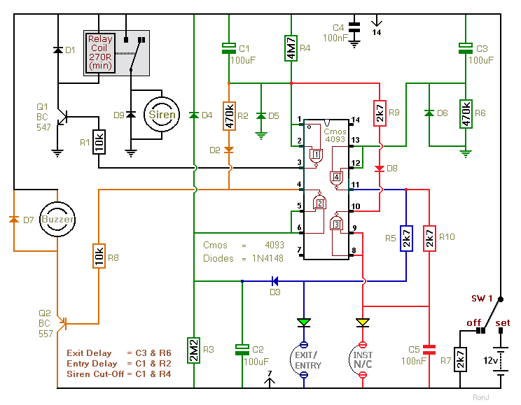
This is a two-zone alarm system featuring automatic exit, entry, and siren cut-off timers. It can be activated by standard normally-closed input devices such as magnetic reed contacts, foil tape, and passive infrared sensors (PIRs). The circuit is designed...