
nicd battery charger schematic

The described circuit operates as a NiCd battery charger capable of handling various battery voltages, specifically 2.4V, 4.8V, and 9.6V. The core component, the LM317T voltage regulator, is configured to provide a stable output voltage suitable for safely charging these battery types. The LM317T is well-regarded for its versatility, featuring internal protections that enhance the reliability of the charging process.
The circuit design incorporates a center-tap transformer, which steps down the mains voltage of 220V to a lower AC voltage of 9V-0-9V. This transformer is essential for isolating the circuit from the mains supply while providing the necessary voltage levels for the LM317T to function effectively. The center-tap configuration allows for the generation of both positive and negative voltages, which is beneficial for creating a dual output that can be utilized in various applications.
The output from the transformer is rectified using a bridge rectifier arrangement, converting the AC voltage to a pulsating DC voltage. Following this, a smoothing capacitor is employed to reduce voltage ripple, ensuring that the input to the LM317T is stable and within the required operational limits.
The LM317T is configured with appropriate resistors to set the output voltage according to the battery being charged. This adjustable feature allows the circuit to cater to different battery voltages by simply changing the resistor values. Additionally, a current limiting resistor can be incorporated to prevent excessive current from flowing into the battery, which could lead to overheating or damage.
Thermal management is also a critical aspect of this design. The LM317T should be mounted on a heatsink to dissipate heat generated during operation, especially when charging batteries, which can draw significant current. The built-in thermal overload protection of the LM317T will help safeguard the IC from damage due to excessive temperatures.
In summary, this NiCd battery charger circuit effectively utilizes the LM317T voltage regulator and a center-tap transformer to provide a safe and efficient charging solution for multiple battery voltages. The design emphasizes reliability, safety, and adaptability, making it suitable for a variety of charging applications.The circuit is able to charge 2. 4V, 4. 8V, and 9. 6V NiCd batteries. The LM317T IC showed in this NiCd battery charger schematic is use to regulate the voltage to battery charge the NiCd batteries as you know that the LM317T IC is a very popular IC from many years, it is a cheap IC with many built in features like current limiter, built in thermal o verload protection, safe area protection etc. The circuit is using center-tape transformer, which is input 220 and output is 9V-0-9V. 🔗 External reference
Related Circuits
The circuit described is suitable for indicating the capacity of a battery using a low-cost electric clock. By connecting a resistor across the battery terminals, the battery discharges at a faster rate than it would with the clock alone....
Using a magnetic compass, ensure that both pickups have a South polarity on the top of each pickup. Verify this by checking for a North polarity on the bottom of the pickups. It is uncommon to find both pickups...

Create a robotic team mascot for a workplace. The initial phase of this project involved designing a charger for the robot's batteries. The aim was to develop a charger compatible with various NiMH battery packs ranging from 700 mAh...
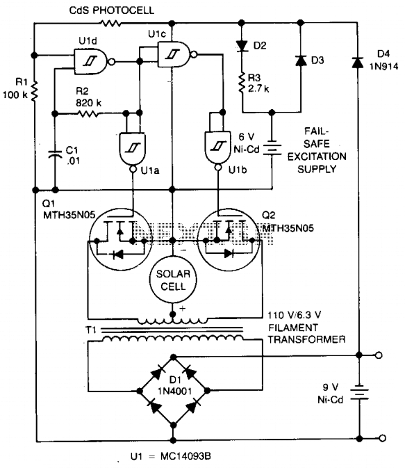
The circuit charges a 9-V battery at approximately 30 mA per input ampere at 0.4 V. U1, a quad Schmitt trigger, operates as an astable multivibrator to drive push-pull MOSFET devices Q1 and Q2. Power for U1 is derived...
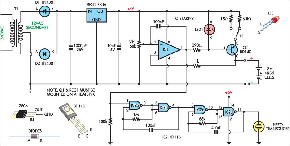
This circuit charges two NiCad cells with a constant current and features dual charging rates, voltage cutoff, and an audible alarm. The circuit is powered by a 12VAC center-tapped mains transformer, along with two rectifier diodes (D1 & D2)...
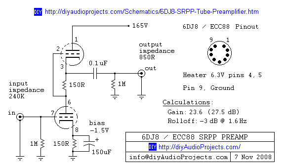
6DJ8 / ECC88 Symmetrical SRPP Tube Preamplifier Schematic. The gain of the preamp is 27 dB (approximately 23.5 times). The 6DJ8 / ECC88 symmetrical SRPP (Shunt Regulated Push-Pull) tube preamplifier schematic is designed to provide a high level of gain...