
Fully Automatic Emergency Light
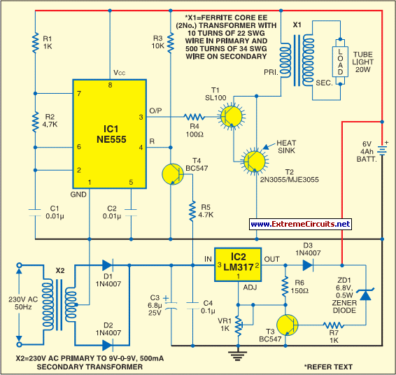
The circuit design effectively integrates an inverter and a charger, ensuring that the emergency lighting system functions seamlessly. The NE555 timer's configuration as an astable multivibrator is critical for generating the necessary square wave to drive the tube light. The choice of a Darlington pair enhances the current amplification needed to operate the ferrite transformer, which is essential for lighting the tube. The transformer construction details provide insight into the winding specifications, which are vital for achieving the desired electrical characteristics and efficiency.
The charging section of the circuit employs the LM317 regulator, which is known for its adjustable output voltage capabilities. This feature is particularly useful for ensuring that the battery receives the appropriate charging voltage, which is crucial for battery longevity and performance. The inclusion of zener diode ZD1 serves as an important safety measure, preventing overcharging by cutting off the charging current once the battery reaches a specific voltage threshold.
Overall, the schematic represents a well-thought-out design that balances functionality and safety, making it suitable for emergency lighting applications. The assembly instructions highlight the importance of proper PCB layout and enclosure design to ensure reliable operation and ease of use.The charging circuit stops automatically when the battery is fully charged. So you can leave the emergency light connected to AC mains overnight without any fear. The circuit can be divided into inverter and charger sections. The inverter section is built around timer NE555, while the charger section is built around 3-terminal adjustable regulator LM317. In the inverter section, NE555 is wired as an astable multivibrator that produces a 15kHz squarewave. Output pin 3 of IC 555 is connected to the Darlington pair formed by transistors SL100 (T1) and 2N3055 (T2) via resistor R4.
The Darlington pair drives ferrite transformer X1 to light up the tubelight. For fabricating inverter transformer X1, use two EE ferrite cores (of 25G—13G—8mm size each) along with plastic former. Wind 10 turns of 22 SWG on primary and 500 turns of 34 SWG wire on secondary using some insulation between the primary and secondary.
To connect the tube-light to ferrite transformer X1, first short both terminals of each side of the tube-light and then connect to the secondary of X1. (You can also use a Darlington pair of transistors BC547 and 2N6292 for a 6W tube-light with the same transformer.
) When mains power is available, reset pin 4 of IC 555 is grounded via transistor T4. Thus, IC1 (NE555) does not produce square-wave and emergency light turns off in the presence of mains supply. When mains fails, transistor T4 does not conduct and reset pin 4 gets positive supply though resistor R3.
IC1(NE555) starts producing square wave and tube-light turns on via ferrite transformer X1. In the charger section, input AC mains is stepped down by transformer X2 to deliver 9V-0-9V AC at 500mA. Diodes D1 and D2 rectify the output of the transformer. Capacitors C3 and C4 act as filters to eliminate ripples. The unregulated DC voltage is fed to IC LM317 (IC2). By adjusting preset VR1, the output voltage can be adjusted to deliver the charging voltage. When the battery gets charged above 6. 8V, zener diode ZD1 conducts and regulator IC2 stops delivering the charging voltage. Assemble the circuit on a general-purpose PCB and enclose in a cabinet with enough space for the battery and switches.
Connect a 230V AC power plug to feed charging voltage to the battery and make a 20W tube outlet in the cabinet to switch on the tube-light. 🔗 External reference
Related Circuits
A modified piezoelectric ceramic acoustic-electric transducer is utilized to create a sound and light control system for a stairway walkway with a delay lighting switch. The circuit structure is relatively simple, consisting of diodes VD1 to VD4 and a...
A dancing light can be easily constructed using a 555 timer wired in astable mode. This circuit alternately blinks two LEDs with a certain delay and can be modified to include additional LEDs or to control incandescent lamps. The...
This circuit is an IC-controlled emergency light. It automatically switches on the light during a mains failure and includes a battery charger with overcharge protection. When the mains power is absent, relay RL2 is in a de-energized state, supplying...
This is a capacitor power supply. This is a very small current of energy-effective because it has very little loss, much smaller than the miniature transformer. Capacitor impedance is inversely proportional to frequency. This is a great disadvantage when...
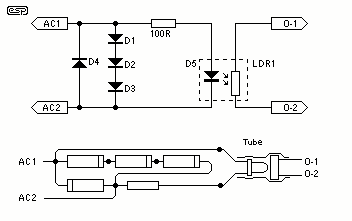
The circuit of the mains current detector is shown in Figure 1. By using a few cheap diodes, a resistor, LED and LDR, a simple opto-isolated detector can be created. This entire circuit dissipates very low power, and can...
The system operates solely on vacuum. Upon inspection of the vacuum hoses, two brittle hoses were found that ran through the firewall to the headlight switch, where a slight hissing sound was noticeable when the lights were activated. Touching...
Warning: include(partials/cookie-banner.php): Failed to open stream: Permission denied in /var/www/html/nextgr/view-circuit.php on line 713
Warning: include(): Failed opening 'partials/cookie-banner.php' for inclusion (include_path='.:/usr/share/php') in /var/www/html/nextgr/view-circuit.php on line 713