
Load Sensing Automatic Switch

The mains current detector circuit utilizes a minimalistic design to achieve effective opto-isolation while detecting AC current. The primary components include low-cost diodes, a resistor, an LED, and a light-dependent resistor (LDR). The diodes are arranged to rectify the AC mains current, allowing the circuit to operate with minimal power dissipation.
The LED serves as an indicator, illuminating when current is detected, while the LDR is utilized to enhance the opto-isolation aspect of the circuit. The heatshrink wrapper serves a dual purpose: it protects the circuit from accidental contact with live wiring and shields the LDR from ambient light, ensuring accurate detection of current.
The circuit has been tested to detect currents as low as 10mA, demonstrating its sensitivity and effectiveness. At a load of 0.5A, the circuit operates without distress, although it is noted that the diodes may become warm under higher current conditions. It is crucial to adhere to the specifications of the components used; the current rating of the diodes is a critical factor, as the circuit is designed for a maximum switched load of 1A. For applications requiring higher current detection, the use of diodes rated for higher currents is strongly recommended to prevent component failure.
This circuit design exemplifies a practical solution for current detection in various applications, leveraging simple components for reliable operation while maintaining safety standards.The circuit of the mains current detector is shown in Figure 1. By using a few cheap diodes, a resistor, LED and LDR, a simple opto-isolated detector can be created. This entire circuit dissipates very low power, and can safely be housed in a heatshrink wrapper to ensure that contact with live wiring is not possible.
This will also keep light away from the LDR. These are cheap and easy to use. I found that I could detect as little as 10mA of mains current with this circuit, and no distress was created at 0.5A. The diodes will get very warm at higher currents. Note that because of the 1A diodes used, this is the absolute maximum current of the switched load. If a higher current is expected, you must use high current diodes to prevent failure. I shall leave it to the reader and the local electronics supplier t 🔗 External reference
Related Circuits
This is an ultrasonic motion detector circuit with high movement sensitivity. It can detect even minor air movements, such as hot air rising or wind blowing, when the trimpot is adjusted to a sensitive position. The transmitter emits a...

Transistors Q1 and Q2 form a flip-flop configuration, while Q3 operates a reed relay. Upon initial power application to the circuit, Q1 and Q3 are in a conducting state, whereas Q2 remains off. A momentary closure of switch S1...
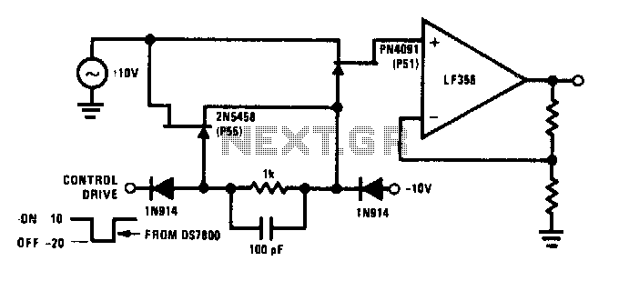
The commutator circuit delivers low impedance gate drive to the PN4091 analog switch for both on and off drive conditions. This circuit also achieves near-ideal gate drive conditions for high-frequency signal handling by offering low AC impedance during off...

This circuit will disconnect the line supply to audio or video equipment if there has been no input signal for approximately 2 seconds. Switch SI provides manual operation, while switch S2 functions as a reset mechanism. This circuit allows...
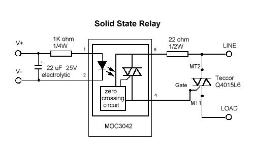
The AQV20 series is suitable for driving an AC relay coil, provided that the de-energizing back EMF from the relay coil does not exceed the 600V rating. It consists of a diode in series with a conducting MOSFET. To...
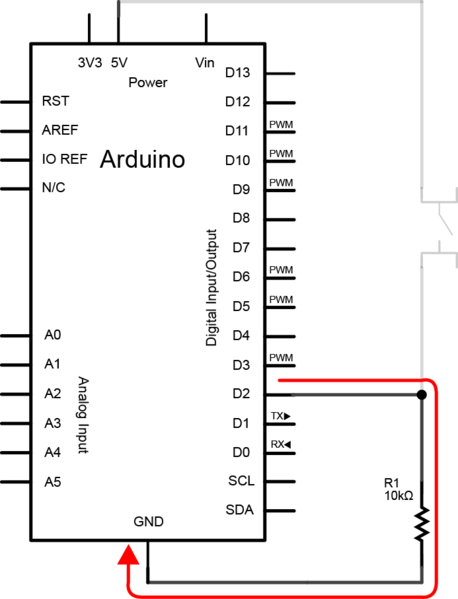
To create the circuit, connect a switch as an input and an LED as an output to the Arduino. The components required include a switch, an LED, a 10kΩ resistor, a 470Ω resistor, a blue or yellow jumper wire,...