
Funk box

This circuit utilizes two key potentiometers, R4 and R7, to manipulate audio frequency response. Potentiometer R4 functions primarily as a feedback control in an oscillator circuit. When R4 is adjusted to a certain threshold, it allows the circuit to enter a state of oscillation, producing a whistle-like sound. This phenomenon occurs when the gain of the circuit reaches unity, leading to sustained oscillations. The precise point at which this occurs can be critical for achieving the desired audio effect.
Once R4 is set to the oscillation point, it is essential to back off the adjustment slightly until the oscillation ceases, ensuring stable operation without unwanted continuous feedback. This adjustment allows for fine-tuning of the circuit's response, preventing distortion or excessive noise.
Potentiometer R7 serves as a tone control, enabling the user to modify the output frequency range. By rotating R7, the user can shift the tonal balance from lower frequencies (bass) to higher frequencies (treble). This is achieved by altering the resistance in the signal path, which affects the cutoff frequency of the circuit. The interaction between R4 and R7 allows for a versatile range of audio effects, making this circuit suitable for applications requiring dynamic tonal adjustments.
In summary, the combination of R4 and R7 provides a powerful means of controlling audio frequency response, allowing for both oscillation generation and tonal variation across a broad spectrum. Proper adjustment of these components is crucial for achieving the desired audio characteristics in the application.Adjusting potentiometer R7 adds extra twang from way down low to way up high. To set the unit, adjust potentiometer R4 until you hear a whistle (oscillation); then back off R4 until the oscillation just ceases. The effect can be varied from bass to treble by R7.
Related Circuits
This compact circuit is designed to eliminate the clutter of surplus small AC mains adapters from a desktop environment. The circuit functions as a smart DC power box. The circuit operates by consolidating multiple AC to DC power conversions into...
500 Series immersion temperature probe, NTC, 100,000 Ohm, ±1.5 °C [±2.7 °F] tolerance, 10 °C to 260 °C [50 °F to 500 °F] accuracy, stainless steel, bullet housing, flying leads (two), 26 gauge Teflon insulation, 4,267 mm [168 in]. The...
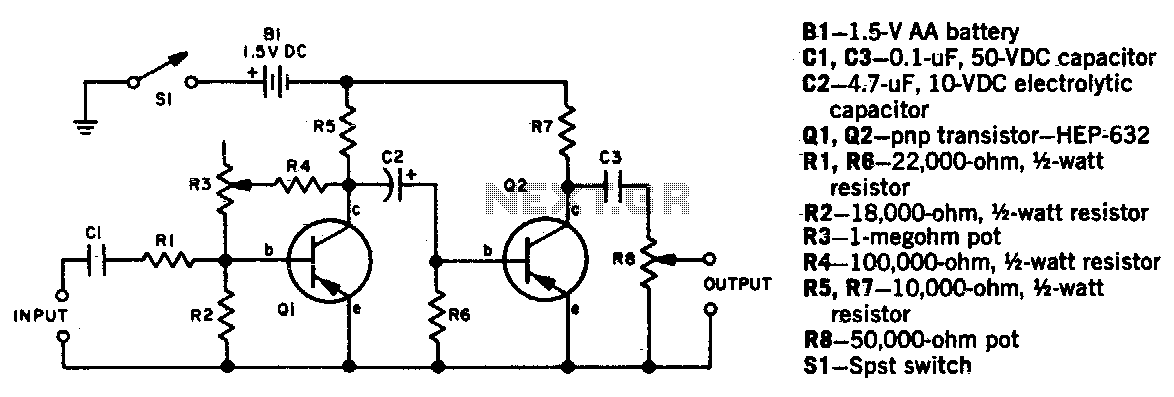
Potentiometer R3 adjusts the degree of fuzz, while R8 controls the output level. Due to the inability of R3 to completely eliminate the fuzz effect, a bypass switch is necessary to connect the input directly to the output terminals...
This circuit creates a buzz coil using a standard automotive ignition coil. A 556 dual timer is employed to establish the frequency and duty cycle of the coil current. One timer functions as an oscillator to generate the 200...
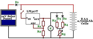
The circuit is designed to power a CCTV camera, provide lighting inside a nestbox, and charge batteries using a photovoltaic (PV) solar panel. It includes a circuit diagram for a solar-powered wireless CCTV camera with battery backup. D1 is...
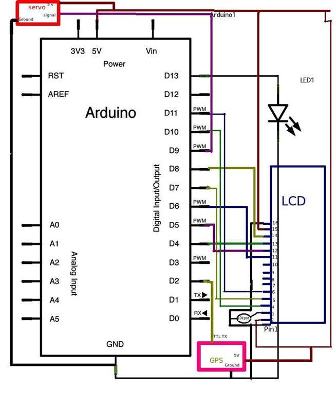
If you have never heard of geocaching, it is a type of treasure hunt played worldwide. GPS coordinates serve as clues, and players must locate a cache box. Typically, there is a logbook for recording names and a small...