
Nestbox Solar Powered Wireless CCTV Camera Circuit

The circuit operates effectively as a solar-powered system, ensuring that the CCTV camera remains functional while providing sufficient illumination for the nestbox environment. The Schottky diode D1 is crucial for preventing reverse current flow, thus protecting the battery from discharging through the solar panel at night. The choice of the 1N5817 diode is particularly advantageous due to its low forward voltage drop, which maximizes the efficiency of the solar charging process.
The ultrabright LEDs D2 and D3 serve to provide adequate lighting, which is essential for visibility within the nestbox. The use of resistors R3 and R4 is critical in limiting the current to the LEDs, preventing potential damage from excessive current. The inclusion of the variable resistor R5 allows for user-adjustable brightness, accommodating different lighting conditions or user preferences.
The voltage regulation is managed by the LM317T, which ensures that the output voltage remains stable at just over 8 volts, suitable for the operation of both the CCTV camera and the LED lights. The resistors R1 and R2 are selected to set the desired output voltage, providing a reliable power source. The manual switch incorporated into the circuit design offers flexibility for the user to activate or deactivate the CCTV camera as needed, enhancing the overall functionality of the system.
This circuit exemplifies a well-integrated approach to powering a wireless CCTV camera in a remote location, utilizing renewable energy sources while ensuring operational efficiency and user control.Below is the circuit used to power the CCTV camera, provide lighting inside the nestbox, and charge batteries from a PV solar panel. Circuit diagram for CCTV powered by Solar Panel with Battery Backup Nestbox Solar Powered Wireless CCTV Camera Circuit D1 is a Schottky Diode used to prevent battery charge escaping through the solar panel at night.
Something like a 1N5817 (1 Amp 20 Volt diode) will do the job and it has a very low voltage drop of under 0. 45 Volts. D2 and D3 are ultrabright LEDs used to illuminate the inside of the nestbox. R3 and R4 are resistors chosen (400+ Ohms) to ensure that no more than 30mA of current gets to the sensitive LEDs, with R5 (a 10k variable resistor) used to increase the resistance and therefore dim the LED s if they are too bright.
The LM317T is a voltage regulator * used to bring the voltage of the solar panel and batteries down to just over 8 volts using resistors R1 (270 Ohm) and R2 (1500 Ohm) to set this value. K is the wireless CCTV camera. A switch (not labelled) is used to manually turn the camera on and off as required. 🔗 External reference
Related Circuits

This circuit is a Phase-Locked Loop (PLL) system designed for use as an FM demodulator. The output of the Voltage-Controlled Oscillator (VCO) follows the FM signal, with the input voltage to the VCO being proportional to its output frequency....
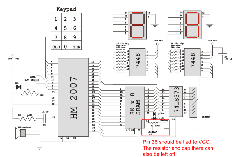
Verify the pin configurations on the datasheets for the integrated circuits used in your project, making necessary adjustments. In this instance, the RAM chip utilized had a non-inverted enable signal on pin 26, while the schematic assumed it was...
Do not drink and drive. Wishing you a safe journey home. Language Integrated Circuits. Language Integrated Circuits (LICs) are specialized electronic components designed to facilitate the processing of language-based data within various applications. These circuits integrate multiple functions, such as...
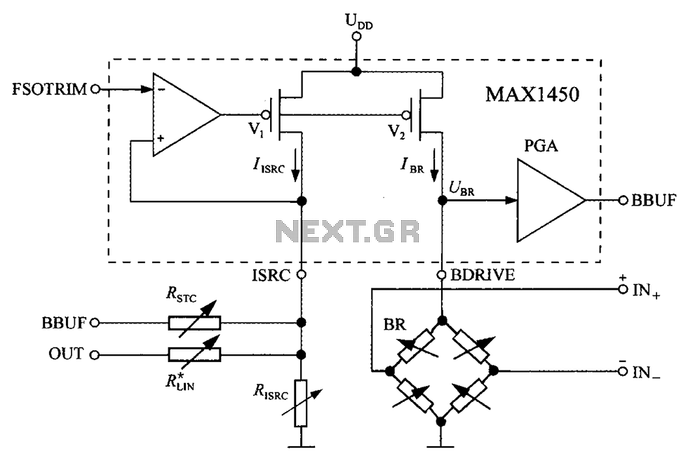
The circuit diagram for the bridge integrated pressure signal conditioner MAX1450 is composed of various components. The MAX1450 is a high-performance integrated circuit designed for signal conditioning in pressure sensing applications. It is particularly suited for use with resistive bridge...
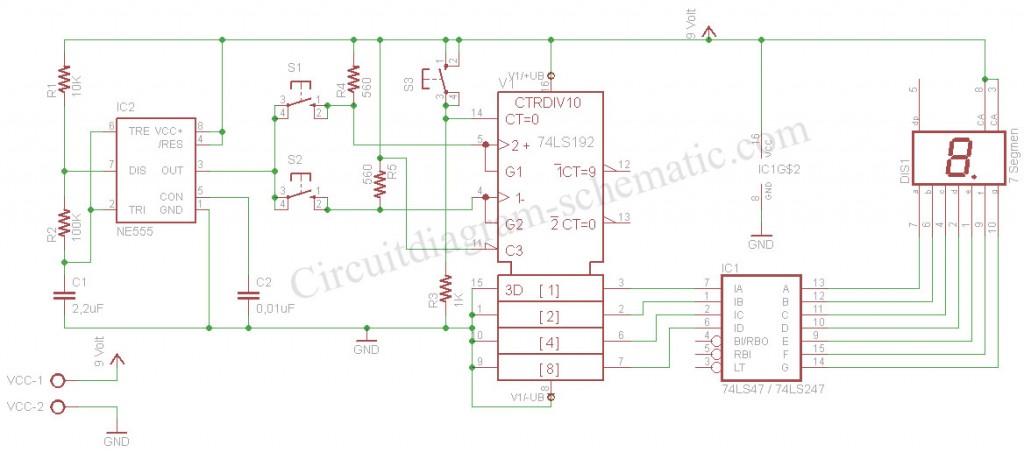
The digital scoreboard circuit is designed to display numerical values ranging from 0 to 9 on a 7-segment display. This display utilizes a common anode configuration. The digital scoreboard circuit operates by controlling a 7-segment display that utilizes a common...
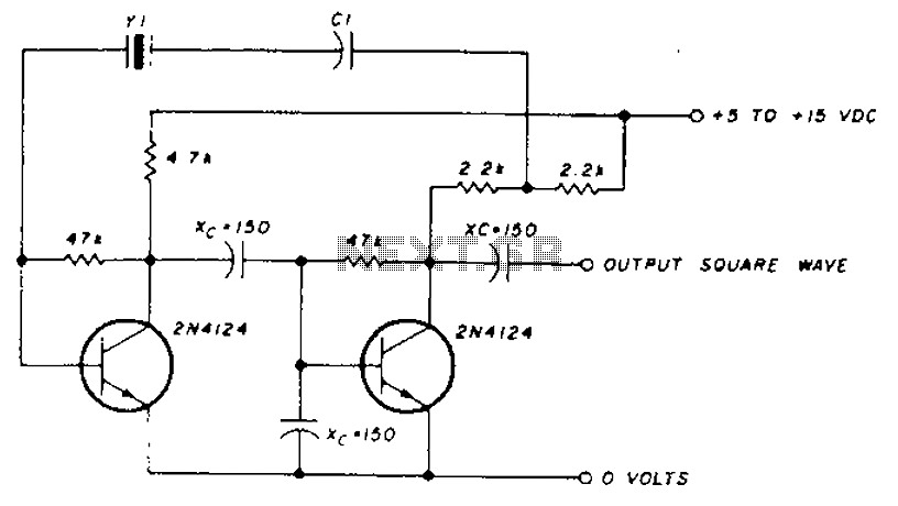
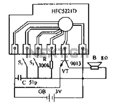
A transistor in series with capacitor C1 can be utilized to adjust the oscillator output frequency. The frequency may vary with changes in capacitance ranging from 20 pF to 0.01 µF, or as determined by the tuning capacitor. The...