
Fuzz Box Distortion Pedal Guitar Effect

The circuit design begins with a high-gain amplification stage utilizing the 741 operational amplifier. This op-amp is configured in a non-inverting configuration to maximize the voltage gain while maintaining a high input impedance, which is crucial for preserving the integrity of the guitar signal. The gain can be adjusted by incorporating feedback resistors in the circuit, allowing for flexibility in the amplification level based on the desired output characteristics.
Following the amplification stage, the signal is routed to a symmetric clipping section composed of parallel diodes. This clipping stage is essential for shaping the tonal characteristics of the guitar signal, introducing harmonic distortion that enhances the richness and sustain of the sound. The parallel configuration of the diodes allows for clipping in both the positive and negative halves of the waveform, resulting in a balanced distortion effect.
The choice of diodes in this stage can significantly influence the sound; silicon diodes will yield a different clipping response compared to germanium diodes, often resulting in a warmer tone. Additionally, the forward voltage drop of the diodes will affect the onset of clipping, allowing for further customization of the effect.
The output of the circuit can be connected to the guitar amplifier or further processing effects, ensuring compatibility with standard audio equipment. Proper power supply decoupling should be implemented to minimize noise and ensure stable operation of the op-amp. Overall, this circuit design provides a robust foundation for creating a versatile guitar effect that can be tailored to various musical styles.This guitar effect circuit uses a simple high gain amplification, followed by a symmetric clipping using parallel diodes clipper. The gain of the 741 op-amp.. 🔗 External reference
Related Circuits
Tiny, portable guitar amplifiers are beneficial for practice while on the go and in bedroom or living room environments. Typically, they can be powered by batteries and include a headphone output. This project incorporates an FET input circuit with...
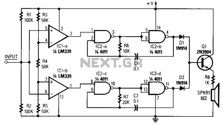
The circuit designed for distortion measurements eliminates the fundamental frequency of 1 kHz, enabling the assessment of the residual harmonic levels. Initially, a true RMS meter is employed to measure the 1-kHz input level (E^) by positioning the switch...
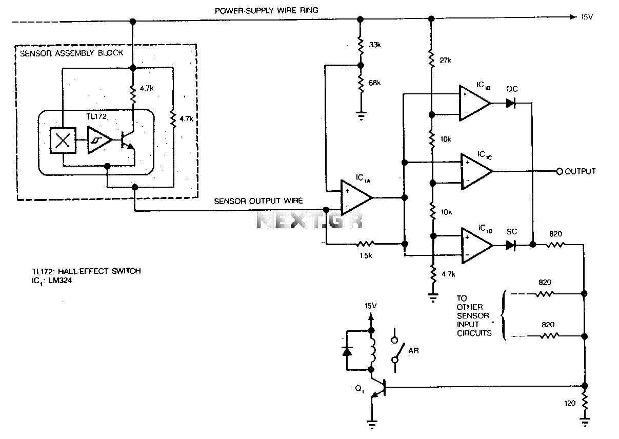
Hall-effect switches have several advantages over mechanical and optically coupled switches. They are insensitive to environmental light and dirt, do not bind, and do not experience mechanical wear. Their major disadvantage is the requirement of three wires per device....
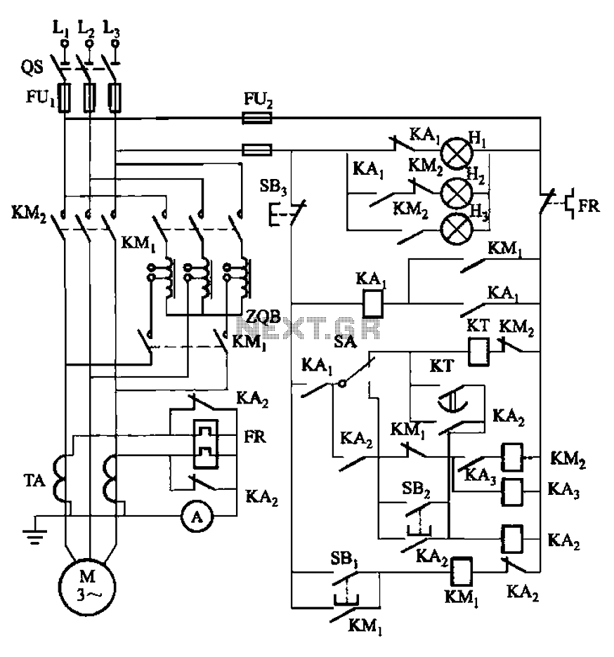
The circuit illustrated in Figure 3-56 features both manual and automatic start-up modes. It incorporates two relays, KA2 and KA3, within the control loop. The circuit design ensures that KM1 is cut off before and after activating KM2. A...
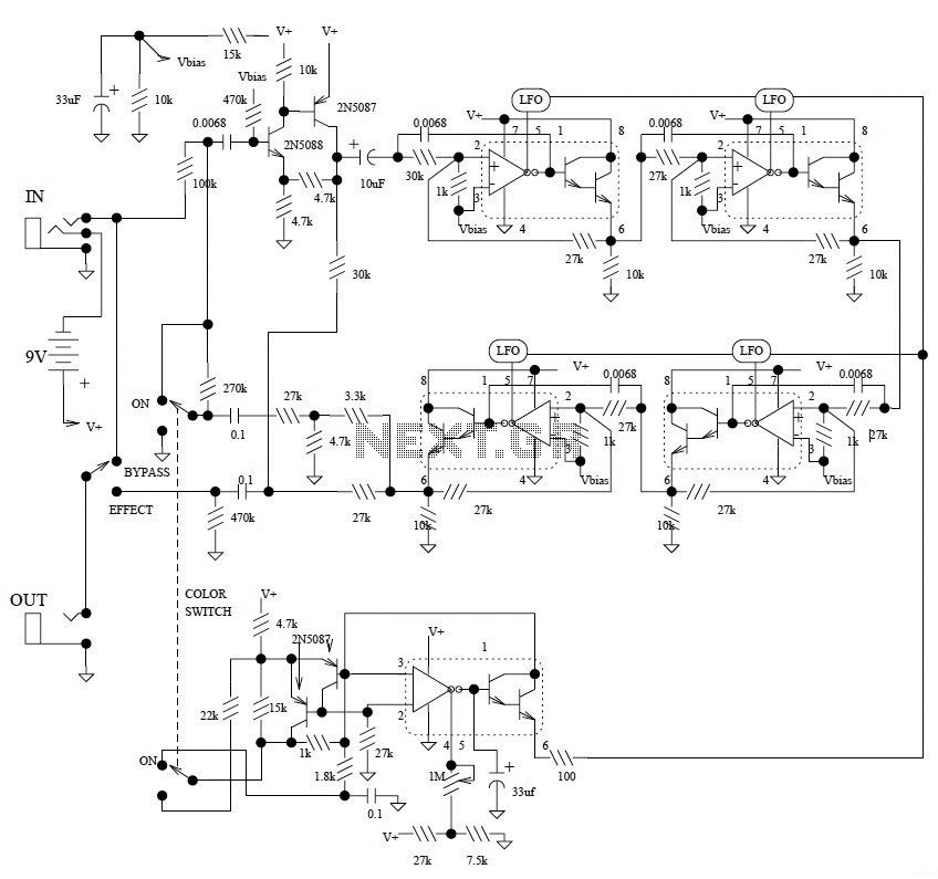
This is the schematic diagram of the Electro-Harmonix Small Stone Phaser guitar effect pedal. The Small Stone is notable for using Operational Transconductance Amplifiers (OTAs) for phase shift stages instead of traditional operational amplifiers. The Electro-Harmonix Small Stone Phaser is...
Observing my Boss pedals and how they were switched on and off I figured there must be more to it. It took me only about 4 hours to design and test this circuit. It works very well and I’m...