
Guitar Effect Bypass Circuit

The described circuit utilizes a 4011 NAND gate integrated circuit (IC) to create a debounced switch mechanism. This is essential in pedal applications where mechanical switches can produce noise and unintended multiple signals when engaged. The debouncing process ensures that only a single, clean pulse is sent to the next stage of the circuit, significantly improving reliability during operation.
Following the debouncing stage, the circuit employs a 4027 JK flip-flop configured in toggle mode. This flip-flop is pivotal for maintaining the on/off state of the effect pedal. When a pulse is received from the NAND gate, the flip-flop toggles its output state, effectively switching the pedal on or off. The JK flip-flop is advantageous in this application due to its ability to change states with each pulse, providing a straightforward means of control without additional complexity.
The overall design emphasizes a clean bypass, which is critical in audio applications to ensure that the signal remains unaffected when the effect is disengaged. The mechanical aspects of the circuit are also designed to minimize noise and ensure smooth operation, contributing to the overall performance of the effect pedals.
This circuit can be integrated into various effect pedal designs, allowing for consistent and reliable switching behavior. The combination of the 4011 NAND gate and the 4027 JK flip-flop provides a robust solution for electronic switching in musical applications, ensuring both functionality and quality in sound processing.Observing my "Boss" pedals and how they were switched on and off I figured there must be more to it. It took me only about 4 hours to design and test this circuit, It works very well and I`m really satisfied with it so I`ll be using it in all the effect pedals I build. It`s a very clean bypass both electronically and mechanically. How it works: the first stage in the schematic is a 4011 nand gate chip set up as a debounced switch to give the logic pulses from the switch to the flip flop. The second stage is the flip flop, this is a 4027 JK flip flop set up in toggle mode, this cont 🔗 External reference
Related Circuits
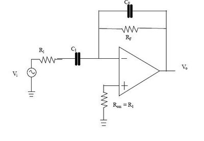
The differentiator circuit is an application circuit derived from mathematical principles influenced by capacitor behavior. The circuit, as illustrated in the accompanying image, is a simple differentiator configuration. To derive the differentiator formula, the following sequence is used: Ic...
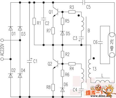
The saving lamp circuit features two main types: glass cover and exposed. The glass cover variants include three series: spherical, cylindrical, and processing types. The first two series consist of four variations: transparent, carved, engraved, and white. These lamps...

Many brands in Asia utilize ultrasonic remote control switch circuits, with some employing relays and others utilizing thyristors. The remote control transmitter is of a puffer type, featuring an ultrasound flute with both olive and flat circular shapes. This...
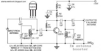
The input coil L1 is composed of four turns of 20 SWG enamelled copper wire, wound slightly spaced over a 5 mm diameter former. It is tapped at the first turn from the ground lead side. Coil L2 is...
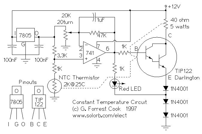
Constant Temperature Circuit. G. Forrest Cook 1997. Introduction: This circuit is a generic low-power temperature controller that can be used for stabilizing temperature. The constant temperature circuit described is designed to maintain a stable temperature in various applications, utilizing low...
This circuit generates dual-tone bell sounds similar to those found in standard doorbell units. It is applicable in various contexts beyond doorbells. The circuit, as depicted in the diagram, produces a "Ding-tone" when switch P1 is pressed and a...