
Fuzz Guitar Effect circuit

The described fuzz circuit is a compact design that effectively generates the characteristic distortion associated with fuzz effects in electric guitar applications. The circuit utilizes a combination of resistors, capacitors, diodes, and an operational amplifier to achieve its sound.
The resistors include two 100K ohm resistors (R1 and R2), a 1K ohm resistor (R3), and a 1M ohm resistor (R4). The 100K ohm resistors are typically used in the input stage to set the gain and help define the input impedance of the circuit. The 1K ohm resistor likely serves to limit current in certain parts of the circuit, while the 1M ohm resistor can be used in feedback configurations to shape the gain of the op-amp.
Capacitors play a crucial role in shaping the frequency response of the fuzz effect. The circuit includes a 100uF electrolytic capacitor (C1) which is likely used for coupling or bypassing to filter out unwanted DC components. The two 0.47uF ceramic disc capacitors (C2 and C3) are typically employed for high-frequency filtering, ensuring that the fuzz effect maintains clarity without excessive noise.
The circuit also incorporates two 1N4148 diodes (D1 and D2) which are essential for creating the clipping characteristic that produces the fuzz sound. These diodes operate in the feedback loop of the op-amp (U1), allowing for asymmetrical clipping of the audio signal, which contributes to the distinctive tonal quality of fuzz effects.
The operational amplifier used in this circuit is a 741 op-amp (U1), a popular choice for audio applications due to its low noise and high gain characteristics. The op-amp configuration can be set up to amplify the input signal and drive the diodes into clipping, producing the desired fuzz effect.
Additional components include a socket for the op-amp, input and output jacks (with a standard mono 1/4" configuration suitable for guitars), wiring, a circuit board, a 9V battery snap for power supply, and an enclosure to house the circuit. The low power consumption of the circuit ensures that a standard alkaline battery can provide power for extended periods, making it practical for musicians who perform regularly.
Overall, this fuzz circuit is designed to be easily integrated into various musical instruments, providing guitarists with a versatile and enduring effect.Fuzz is one of the classic guitar effects, and this simple circuit generates it quite well. The circuit is so compact that it can be built into guitars or amps that do not have built in fuzz to add that capability to the instrument. The circuit does not use much battery power, so a standard alkaline battery will last many years even with daily use.
You can use any input/output jacks you want, but the standard for musical instruments such as guitars is a mono 1/4" headphone plug and jack. R1, R2 2 100K 1/4W Resistor R3 1 1K 1/4W Resistor R4 1 1M 1/4W Resistor C1 1 100uF 16V Electrolytic Capacitor C2, C3 2 0.47uF Ceramic Disc Capcitor D1, D2 2 1N4148 Diode U1 1 741 Op Amp MISC 1 Socket for U1, Jacks for Input/Output, Wire, Board, 9V Battery Snap, Case 🔗 External reference
Related Circuits
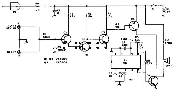
For use with low-power transmitters that require a positive keying voltage. The transistors Q1, Q2, and Q3 are configured as a switching amplifier. When the key is pressed, the collector of Q3 is pulled to ground, which activates Q5...
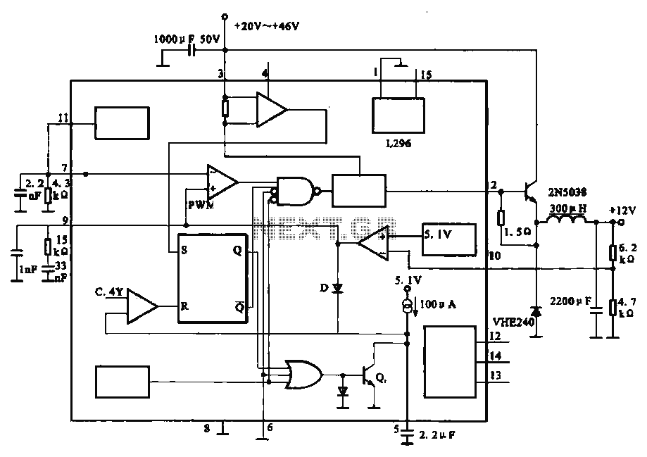
The circuit outputs 12V at 10A and utilizes a high-current switching power supply design based on the L296 component. This configuration allows for an output current of up to 10A, and the entire circuit is compact with minimal component...
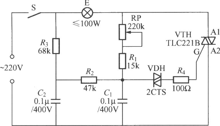
To address the lag and light transition issues, a Triac dimming light circuit featuring a dual time constant can be employed. This circuit enhances the resistor-capacitor network formed by R3 and C2. The reduced charge on capacitor C1 can...
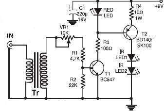
This wireless infrared (IR) headphones circuit project enables the transmission of audio signals through an infrared connection. The circuit consists of two main components: a transmitter and a receiver. Unlike radio frequency (RF) transmitters, both parts of this application...
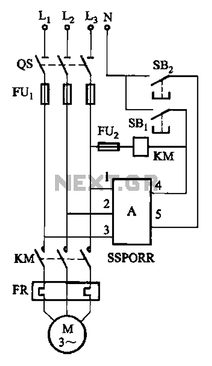
The solid-state phase failure relays for three-phase AC phase failure monitoring, protection, and control of new devices are referred to as SSPORR. This module consists of a five-terminal semiconductor configuration. Terminals 1, 2, and 3 serve as the three-phase...

This design outlines a tracking transmitter for audio tones operating in the FM band frequency. The circuit can function as either a signal transmitter or a remote control transmitter and utilizes only readily available components. It has a transmission...